All too often a dyno is inaccurate, not by design, but due to improper installation in the test cell, the air exchange capability, and/or the electrical and water supply, along with a host of other factors. The best made dyno can provide falsely optimistic or pessimistic data due to operator or installation error. There is much more to dyno testing than just buying the unit. This is why we felt it important to provide this primer prior to our dyno test of our 467 Mule engine.
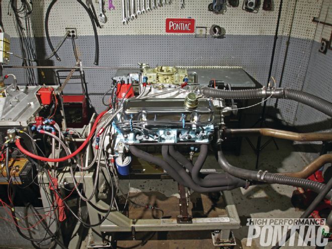 Without the complication of a dyno hat and exhaust gas temperature sensors, the testing and any tuning or changes become much easier on our 467 Mule engine.
RaceKrafters employs a Model 800 Stuska brand water brake that was modified by Depac. It’s integrated with the latest Depac control system and data acquisition. The brake has the ability to hold 2,000 hp, and uses a water supply that enjoys 90 psi of pressure with the load valve closed and about 55-60 psi during a full power pull. A general rule is 10 gallons per minute of water are required for each 100 hp absorbed. A 1,000hp dyno would require about 100 gallons of water per minute at a flow of around 60-70 psi. A 300-gallon tank holds the water for testing and is sent to the brake with a large centrifugal pump. The water is not recycled, so cooling is not a concern. When the water is reused, it then needs to be cooled to allow accurate control of the resistance created by the brake.
The engine is mounted on a stand called a dyno cart and is attached from the flywheel to the water brake with a coupling. The brake has two water lines going to it: an inlet and an outlet. In simple terms, it can be thought of as a water torque converter that causes resistance against the engine. A strain gauge is employed to measure engine torque, which is mathematically converted to horsepower. The equation is:
Horsepower = torque x rpm/5,252
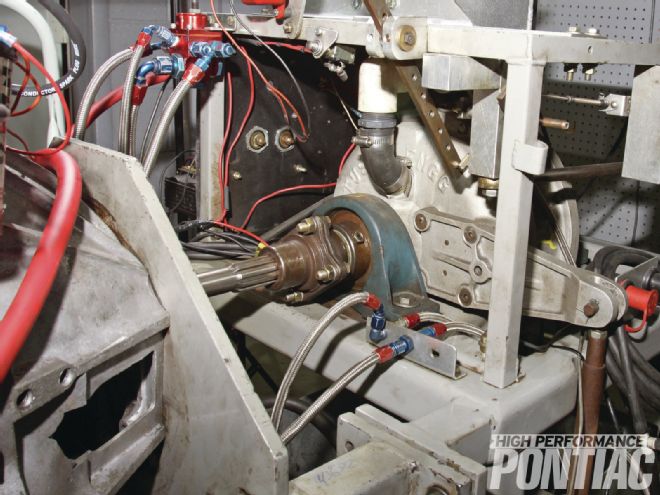 The water brake on a dyno has two impellers just as a torque converter does. The unit uses water to create a resistance, and the torque is measured by a strain gauge that in years past was mechanical but is now electronic.
Horsepower is a calculation that was derived a few hundred years back by James Watt to sell steam engines. With any engine, both horsepower and torque are equal at 5,252 rpm. This is due to the numerator and the denominator being the same and thus, becoming one. If you do not believe this, then get out your calculator and using the dyno sheet from the tuning story that follows, compute the horsepower from the torque and rpm.
A simple way to look at a dyno is the water brake loads the engine until it is pulled down to a certain rpm, and then the torque is read. This procedure can be controlled by the operator with a load (water) valve or though a control system, such as the Depac employed at RaceKrafters. There are a number of companies that make dyno control systems, Depac being one of them. Over the years, most load control manufacturers also integrated data collection, making the PC-based system very accurate and able to provide finite readings.
In contrast, in the good old days the dyno would be operated manually with a load (water) control valve and it would require at least two other people: one to watch the torque meter, while the other watched the tachometer. A pull would be made and then each would report the numbers they saw and the power would be calculated using the equation supplied in this primer.
As you can see, there was a lot of room for error, since the load and the data collection were all based on the skill of the individuals. As the author, my first dyno experience was that way. It often resulted in quite a few verbal arguments when you did not read a value correctly or the dyno operator had trouble controlling the load. Today, a dyno session with modern equipment eliminates all of that.
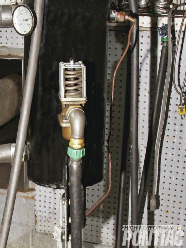 The water tower we used is a standard type that builds no cooling system pressure. A thermostat is used to keep the engine at the desired operating temperature. Heated water is exchanged for fresh from the building water main.
Cooling of the engine while on the dyno is accomplished by a device called a water tower. There are two types: standard and pressurized. Our engine was connected to a standard water tower.
Water is introduced into the engine, and the cooling tower has an adjustable thermostat. When the engine reaches the set point (we ran our test with the coolant around 150 degrees F), it opens and discharges some of the heated water and replaces it with water from the building feed. This system is very effective at maintaining the engine temperature desired, but does not enjoy the benefit of pressure, and thus an engine tested this way is usually set to run a cooler liquid temperature than in the car.
Cooling system pressure (in the vehicle or on the dyno) is used to raise the boiling point three degrees F for every 1 psi over atmosphere. But more important, it allows the coolant to release from the water jacket of the cylinder head when boiling occurs. When an engine is under full load, localized boiling is introduced (not to be confused with boil-over of the radiator) around the passages that cool the combustion chamber and exhaust valve. This boiling can take on different phases. The first stage is identified as nucleate boiling. When it occurs, vapor bubbles form. The pressure is used to move the bubbles from the extremely hot area to a cooler location to allow the coolant to recondense into a liquid and to allow fresh coolant to come in contact with the cylinder head. The boiling-vapor-condensing effect is what actually removes heat from the cylinder head and is the way thermal transfer occurs naturally. It is the inverse of a person sweating on a hot summer day—the evaporation of the perspiration works under the theory of latent heat and cools you.
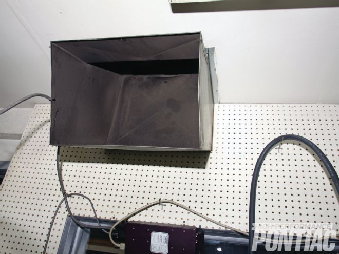 It is important for the dyno cell to be supplied with clean, fresh air. The cell is equipped with a high-pressure fan that draws air from the roof of the building and exchanges it out the rear of the room.
With the basic premise of dyno testing established, the area most important to the Pontiac owner is the data derived from the run. There are many different factors that can be examined during a dyno pull, the most common being: rpm, torque, horsepower, water temperature, oil temperature, oil pressure, fuel pressure, brake specific fuel consumption (BSFC), fuel flow, and rate of acceleration.
Water temperature is usually run around 150 to 160 degrees for a street/strip engine, but may be higher for a road race or towing application. Most operators do not like to pull an engine with water cooler than 140 degrees F and oil below 120 degrees F.
Oil pressure is used to determine the mechanical health of the engine and serves the same purpose as a gauge would in the car—to alert the operator of a problem before the engine is damaged. Modern dynos have a warning system that monitors low oil pressure. As we move forward with this project, you may see a photo of a dyno screen (as in this story) with that prompt. All it means is that we took the image with the engine shut off after the run.
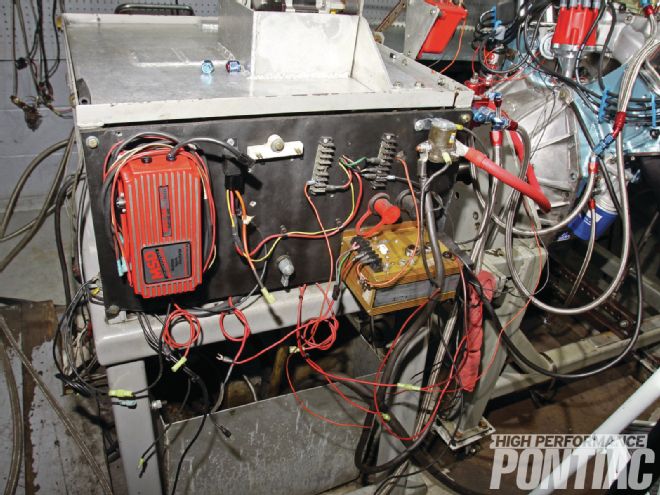 The dyno cell has a hard-wired MSD 6AL that is run with the engine. By attaching this to the dyno, it makes for quicker and easier engine hookups and limits the necessary wiring for each application.
Fuel pressure is usually supplied by an electric pump on the dyno and is set with an adjustable regulator. On a carburetor application, the fuel pressure is set around 7.5 psi.
The real tuning decisions occur by comparing the horsepower and torque, BSFC, fuel flow, and rate of acceleration in rpm per second. BSFC is an indicator of how much fuel in pounds is required to produce 1 horsepower for one hour. Fuel flow is the total fuel sent to the carburetor as read from a flow meter, and is registered in pounds per hour. BSFC is an indicator of the engine’s efficiency to convert chemical into mechanical energy.
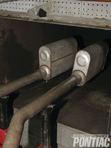 Mufflers are employed to reduce noise for the surrounding businesses and are so large that no backpressure in the engine is created.
The rate of acceleration is also important, since a more powerful and properly tuned engine will accelerate the crankshaft against the load at a quicker pace. It also takes into consideration design factors, such as the mass of the rotating assembly and the internal engine friction from the angularity of the connecting rod from the rod-to-stroke ratio. It is not something that can be tuned, but is an excellent area to study during engine development work.
Some dyno cells also look at a few other areas such as air/fuel ratio, mass airflow or cubic feet of airflow, exhaust gas temperature, and volumetric efficiency. RaceKrafters did not use these areas on an engine such as our Mule and I will explain why.
Exhaust gas temperature is a better indicator of fuel distribution, while designing or modifying an intake manifold when your concern is even flow to all bores. Since we were using a well-designed Edelbrock Torker II intake, there was no need to complicate the test with exhaust temperature probes in each primary header pipe. Many use exhaust gas temperature as a tuning guide, but with today’s reformulated street gas, the burn characteristic is different. This makes it an inaccurate tuning criterion, since often the data looks high with an older-style motor, such as a Pontiac, even when the mixture is not too lean. A rich mixture will lower the EGT, while a lean charge will raise the temperature.
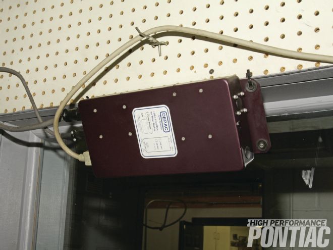 The automated controls on the dyno remove all human error in loading the engine against the water brake. This allows very accurate and repeatable data, which is important during testing of changes and modifications.
Air/fuel ratio is calculated by measuring the incoming air flow using a top-hat airflow meter that is connected to the carburetor, and comparing that with the amount of total fuel flow. The problem is that it doesn’t account for the air that bypassed the rings and went into the oil pan, the storage capacity of the intake manifold, and the air discharged past the exhaust valve on the overlap of the cam. When measured at the carburetor and without assigning values for the areas of loss, the engine looks as if it is consuming more air than it actually is. This skews the air/fuel ratio calculation. On the OE level, engineers are able to accurately measure the losses and can identify the real air throughput of the engine that is being used for combustion.
Since this same reading is employed to determine the volumetric efficiency (VE) or the amount of cylinder fill, it falls prey to the same issues. An engine enjoys the highest level of VE when it produces peak torque. In a normally aspirated application, it is usually around 80 to 85 percent VE or cylinder fill. Forced induction is required to bring that value to 100 percent or greater on a production-style engine, especially with a single intake valve per bore.
A better method to read air/fuel ratio is a linear air/fuel meter that has a very fast acting oxygen sensor. On a race engine that has a very quick rate of acceleration, that data too becomes incorrect unless a very expensive system is used—the events are happening too fast for the information to be real during a transient state. Remember that on the OE level, the concern is with steady state mixture and not with an engine that is accelerating extremely fast, such as a drag car.
For these reasons, the best method to tune an engine such as our test Mule is to measure the power and then alter the BSFC (through carburetor jet and air bleed changes) to achieve the highest numbers. When the best air/fuel ratio and timing curve is obtained, the engine will make the most power. You can tell that it’s happy by its output. It also needs to be recognized that all of our testing is being done at wide-open throttle and that is why some of the measured areas do not apply. For steady state and transient performance, the best place to tune is with the Pontiac on a chassis dyno (which RaceKrafters also has).
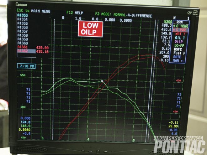 This is a computer graph of one of the many pulls made on the engine. The dyno has a warning for low oil pressure if that would occur. When the engine is shut off and the dyno screen is viewed that prompt is displayed.
All of our testing will be limited to full-throttle passes from approximately 3,000 rpm to 5,500 rpm. The Depac data system was set to take readings in 100-rpm intervals and rounds to a single decimal place. It also registers the average for the entire run from the beginning to the end. Though we all like to look at a dyno sheet for peak power, the average numbers are what will get the Pontiac down the track or the road. A tune that produced higher average power will be faster than a setup that has a better peak number but a lower average. This is especially true on an engine that operates under a transient condition, like a street/strip car. In contrast, a dedicated drag race entry will usually only vary about 1,500 rpm during a run. The average, while still important, will not be as critical.
Hopefully this primer has provided some insight as to how a dyno and its cell are set up to get accurate data, how we will perform our testing, and why we chose the methods we employed.
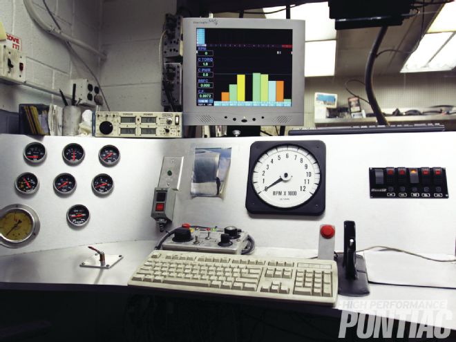
What’s on the Dyno Console?
Just as important as the dyno brake and cell design is the ability to collect data. That is a function of the control console. Looking at our lead photo of RaceKrafters’ console, there are both mechanical gauges and computer monitors.

At left are backup gauges for engine vitals such as oil pressure, water temperature, and so on, with a water pressure gauge for water going to the brake at the bottom.
The water bypass valve to fine-tune water pressure to the brake is to the left of the keyboard. Above it on the console are the red and black on/off buttons for the water brake pump with a light above them to show when it’s on.
Sitting atop the console to the left of the monitor is the Depac data acquisition box. On the wall above it are two rectangular expansion data acquisition boxes for auxiliary sensors.
The computer monitor is one of two, as two complete computer systems are used with one backing up the other. Craig employs this monitor to provide a bar graph of the engine’s vital signs; the other monitor (shown later in the article) plots a graph for the pulls.
Beneath the monitor is a large tach. Below it and ahead of the keyboard is the dyno load controller dash, replete with switches and dials, that automatically controls the load during a pull.
The throttle lever is to the right of the keyboard, and the red button next to it is pressed to begin the data collection and start the pull after the engine is loaded.
On the right side of the console is a bank of switches to control items like the starter, two fuel pumps, the water pump, auxiliary items, and so on.