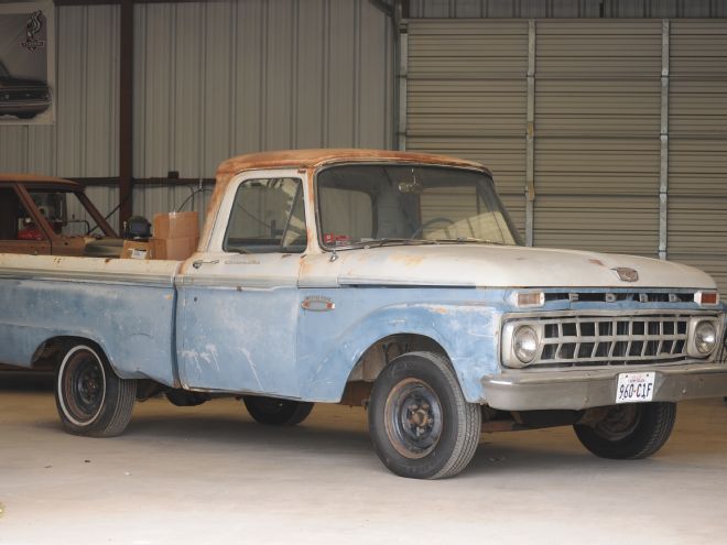
Ford's fourth-generation pickup trucks (1961-1966) are quickly becoming popular, as we keep seeing more and more at each show we attend. Recently we came across a 1965 Ford F-100 that was growing old in a field. The exterior appeared to be in great shape for a 50-year-old truck and just happened to be what we were looking for in a new project. We caught up with the owner and pressed him with the question, "How much?" He tossed out a dollar amount that was such a good deal that we just couldn't afford to pass it up. We reached into our pocket and shelled out the cash that we had stashed for just such an occasion.
Check out Part 2 right here: http://www.hotrod.com/how-to/chassis-suspension/1509-putting-ifs-on-a-1965-ford-f-100-part-2/
While the outside was in good shape, under the hood we could tell that the truck had not been fired up in years. Being that the truck was classified as a roller, we called our buddy, the wrecker guy, and had him haul our latest project back to the shop where we found ourselves staring at our new vehicle and asking ourselves, "Where do we start?"
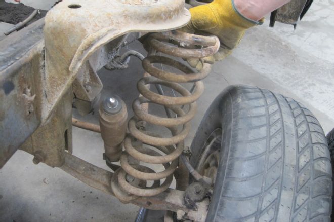
We felt one of the first things that we needed to do was to get it to sit right. We started doing some research and found that putting this truck on the ground was not going to be as easy as we had thought. It seems that, in 1965, Ford changed the front end of their pickups over to a new independent suspension, dubbed the twin I-beam. The twin I-beam provided an independent front suspension that promised to "improve handling on all road and driving conditions." While there is no doubt this suspension more than served its purpose over the years as stock truck suspension, its geometry and design pretty much nix any type of major lowering. While there are a few manufactures who make lowering I-beams kits, these will only provide a drop of a couple inches at most. The only way to get the truck to lay out is to do some minor surgery and replace the front factory crossmember with an aftermarket one.
We had met Justin Padfield, from Scott's Hot Rods, at several shows so we rang him up and told him of our thoughts. He suggested that in order to get the truck on the ground we would need to install one of their weld-in SuperSlam IFS suspension kits. Justin explained that this crossmember will allow us to utilize airbags under the front suspension so that we could lay the truck completely out. "Send it to us!" we said. Understand that this is a custom suspension tailored to your needs so they do not have one for every application on the shelf, so in some cases there is a lead time before your parts are shipped.
For this project Danny over at Strange Daze Rods and Customs agreed to help us install the Scotts IFS. We spent four Saturdays cutting and removing the old parts and cleaning 50 years' worth of grease and grime before we were ready to install our SuperSlam kit.
Once the prep work was completed, it was a simple matter of boxing the frame and mocking the crossmember in place before we were able to weld everything up. We'll tackle the initial fabrication portion of the IFS install this month, returning next time to bolt up the suspension components.
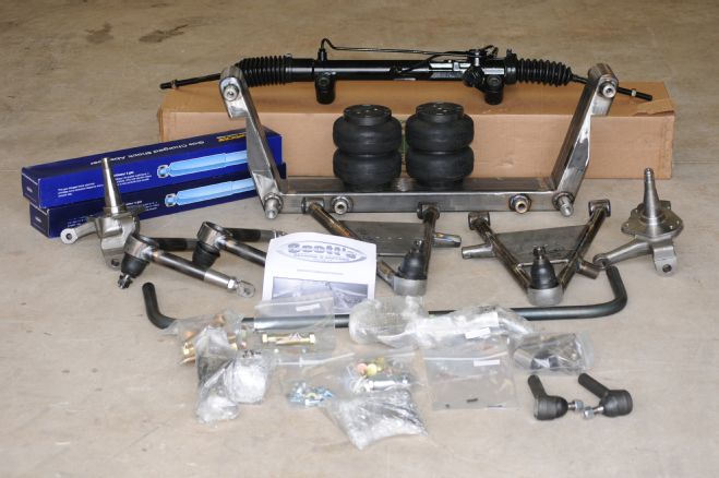
01 This is the Scott's Hot Rods Superslam IFS kit, which contains everything we need to get our Ford dropped and rolling. One of the unique features of the SuperSlam kit is Scott's proprietary one-piece crossmember design that provides extra support to the relatively weak vintage truck chassis. This crossmember design combined with a boxed-style framerail provides an extra strong foundation. Scott's tubular control arms are also very stout and feature a spherical Heim joint for easy camber adjustments and built-in airbag and sway bar mounting points. A front mounted power rack-and-pinion steers a pair of Mustang II-based spindles while a set of Monroe gas shocks will help dampen the bumps in the road.
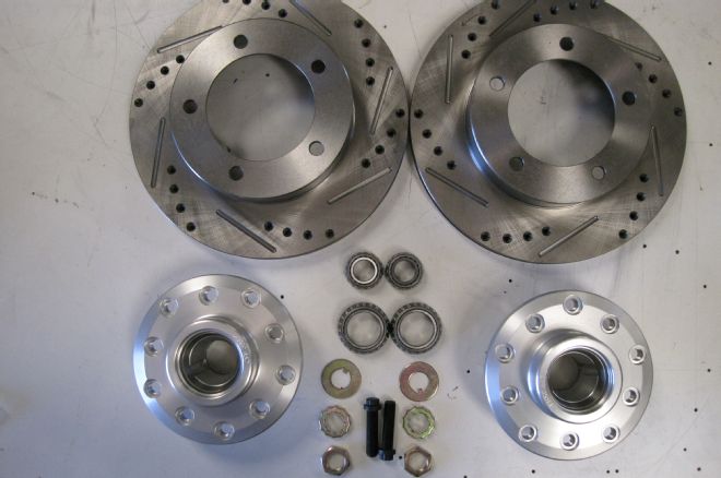
02 Classic Performance Parts provided 11-inch drilled and slotted rotors and aluminum hubs, which will provide plenty of power to stop our F-100.
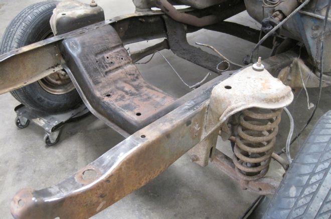
03 After removing the front sheetmetal and original drivetrain, we spent the morning cleaning the chassis in preparation for initial disassembly.
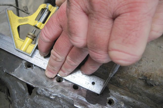
04 Before we get ahead of ourselves however, we need to mark the front axle centerline so that our new crossmember can be placed in the correct spot. It's also a good idea to take a wheelbase measurement at both sides and note that number as well.
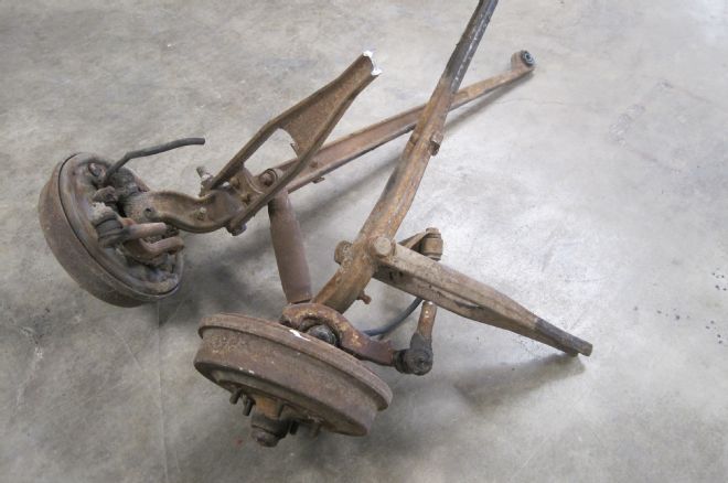
05 Next, the suspension components are removed…
06 …followed by the stock coil spring towers. These need to be removed completely so as to not interfere with the new suspension components.
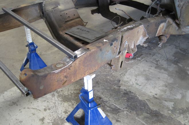
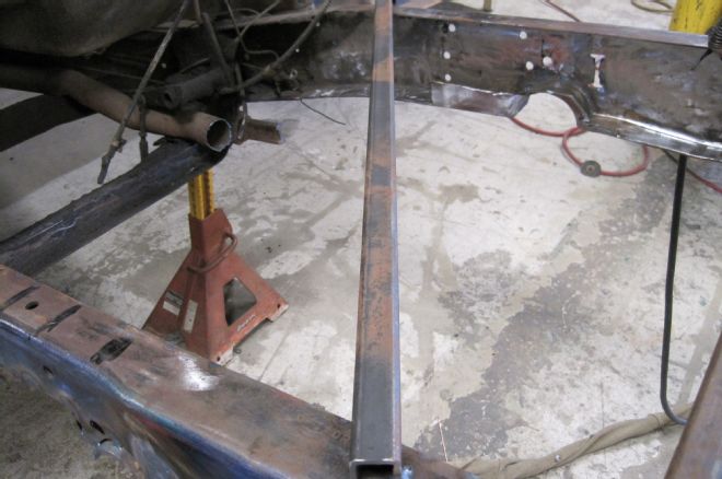
07 Before we remove the original crossmember, two 1-inch square tubing braces are tacked across the framerails to keep the frame from moving. A pair of jackstands serve to support the front of the frame as well.
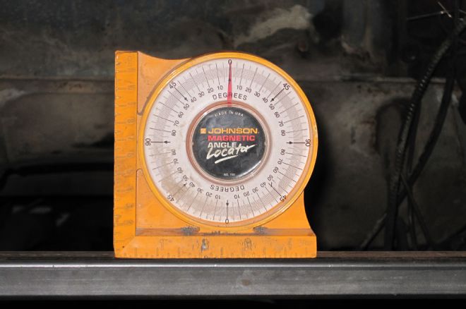
08 The chassis is then double checked for level, side to side and front to rear.
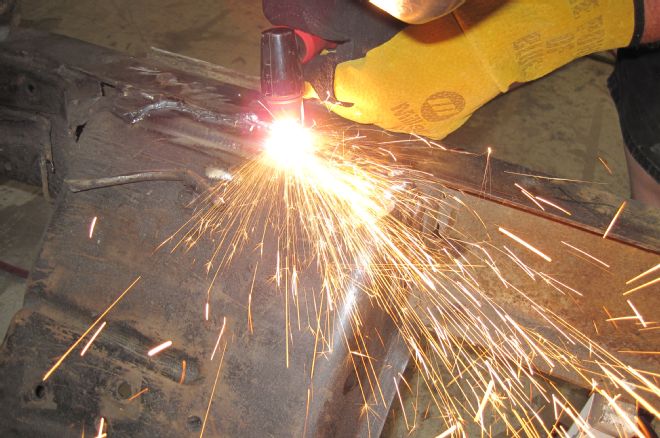
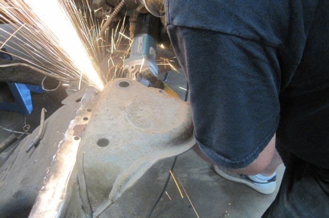
09 With the chassis properly situated, a plasma cutter was utilized to make quick removal of the crossmember.
10 Due to its design, the Ford twin I-beam suspension system requires a more complicated crossmember than traditional straight-axle or IFS designs. Because of this, cutting the unit free of the framerails requires a good bit of energy from the plasma cutter.
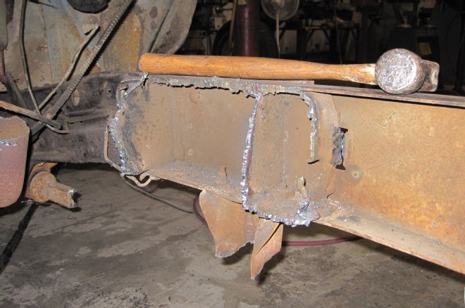
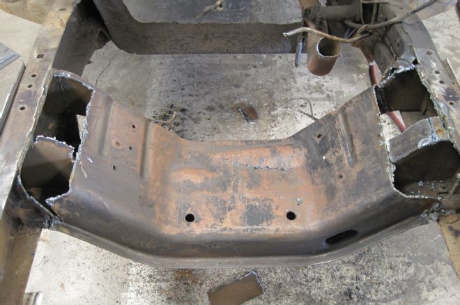
11 Once the center portion of the crossmember is removed, we still need to knock out the riveted portion that is attached to the framerails. While the crossmember could be removed in one piece by knocking out the rivets, it's easier said than done, hence the reason we trimmed it away first.
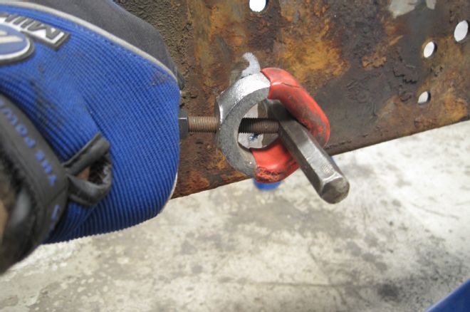
12 Grinding the head of each rivet before driving it out via punch is the best method for removing chassis rivets.
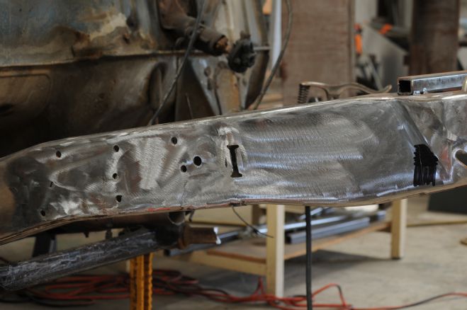
13 Once all the offending stock bracketry was removed, we went over the entire frontend with a 36-grit sanding disc on a pneumatic sander to get everything nice and clean, in preparation for the welding to come.
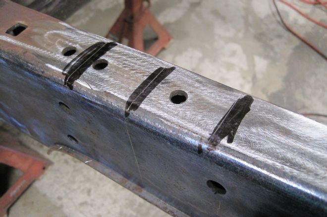
14 Next, it's time to locate the crossmember using the centerline we scribed before initial disassembly. A set of scribe marks 2 inches from the centerline on both sides will serve to locate the crossmember easily.
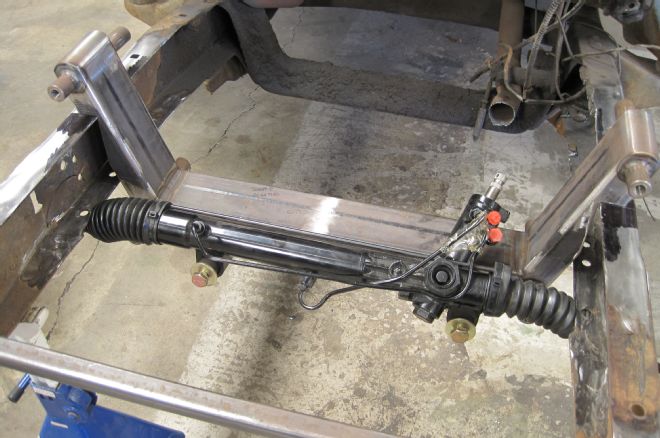
15 Then, the crossmember was set in place with the rack-and-pinion installed. In a stock-height application, the rack and pinion would be low enough so as to clear the bottom of the framerail. In a lowered scenario such as ours, the frame must be notched to allow the rack-and-pinion to clear under full suspension travel.
16 Additionally, we found that further clearance needed to be created to allow full movement of the lower control arms, sway bar, and airbag.
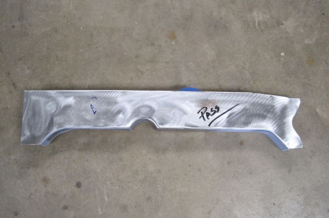
17 Instead of creating three different notches in each framerail, we opted to cut one long step notch and a single C-notch for the steering arms in each framerail. First, a template was created for both framerails from which a pair of matching boxing plates were fabricated.
18 Since our notch is going to remove a significant portion of the structural integrity of our chassis, we welded in another temporary support to ensure that the framerails stay true during fabrication.
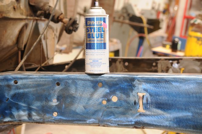
19 Before scribing our cut line on the side of each framerail, a coat of layout fluid is applied to ensure our line is easy to see.
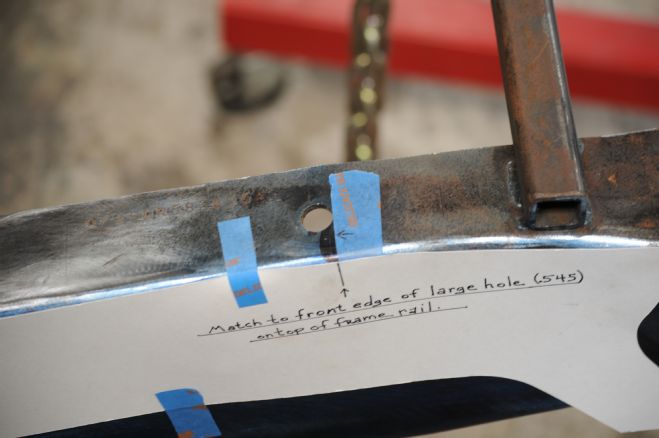
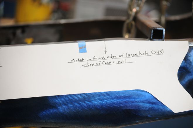
20-21 Our template was then taped in place using the axle centerline and an existing hole as reference points.
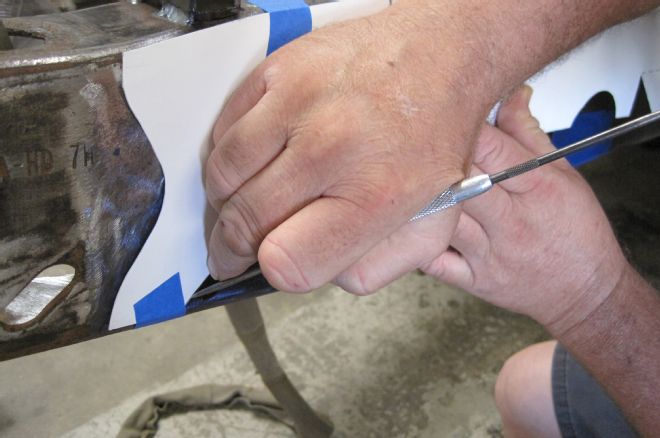
22 Then the cut line was carefully scribed onto the framerail.
23 To make a nice, straight cut, a jigsaw was used to cut the entire notch away from the framerail.
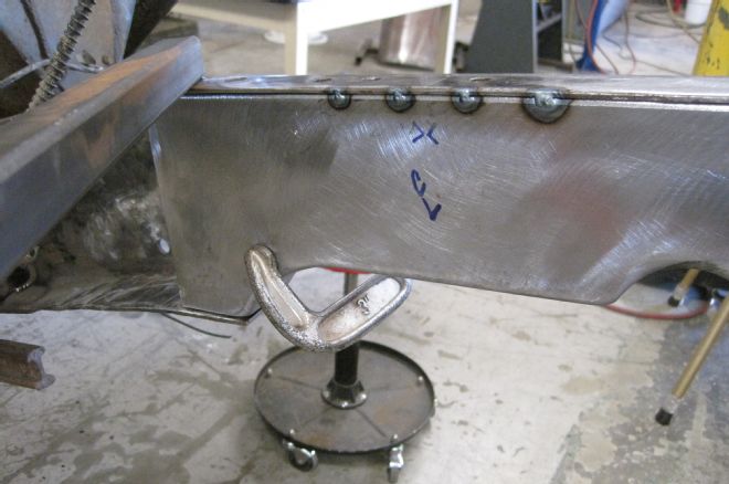
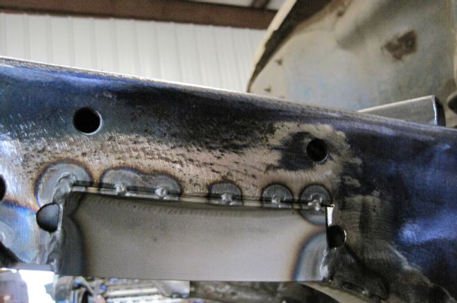
24 With the notch complete, the boxing plates could be clamped and then tack welded in place.
25 As we mentioned earlier, a notch for each airbag needed to be fabricated as well.
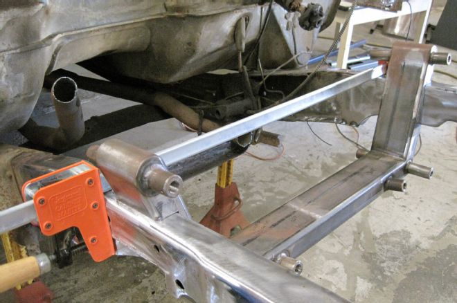
26 Now we're ready to install the front crossmember. Note that the temporary cross brace has been removed. With the crossmember in place and the boxed framerails clamped against the crossmember, it's time to start welding things in place.