One of the most important interfaces between the driver and car is the steering wheel. It’s where your hands go, what you clutch madly in wild-eyed terror when you don’t have seats that hold you firmly in place during hard cornering, and what generally controls the trajectory of your Corvette (hooning notwithstanding). The good news is that Scarlett came with a tilt/telescoping column that easily adjusts to the desired hand position and also makes it easier to get in and out over our well-bolstered Corbeau seats. The bad news is that time did the same things to the column that it did to the rest of the car, and the laser-sharp steering we expect from the steering rack we’ll be installing will be lost in the slop and play of the well-worn steering column. Having looked online for a shop that specializes in rebuilding them and finding only vague results, we sourced a rebuild kit from Paragon Reproductions and dug in ourselves.
Word to the wise: this is not for the faint of heart. Of all the things we’ve done to our beloved Shark, this was one of the most detailed. We’ll give an overview here, but to do it yourself, lay aside the Haynes manual and the assembly book. You’ll need the detailed GM Service Manual and a few specialized tools. Paying close attention to the instructions, though. With unfettered access to the full array of tools available at Tray Walden’s Athens, Alabama-based Street Shop, Inc., we managed to get the column rebuilt in about a day’s work, not counting time to let paint dry. Assuming you have all the parts on hand, it’s basically a weekend project.
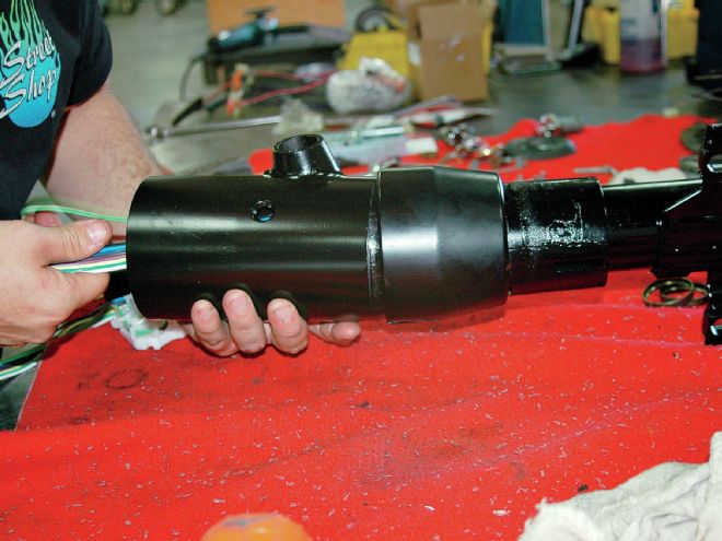
Some of the column rebuild can be done in the car, but not all, so the first order of business is to unplug the wiring from its plug on the column, back out the assorted bolts holding it in place, loosen the rag joint, and pull the column away from the firewall and up and out of the car. We had already removed the seats and other dash components when we pulled the column, but if you still have those in place, they should probably come out, too.
The first order of business was to pry off the center emblem/horn button and remove the wheel. Since GM steering wheels from that era tend to be slick at best and sticky at worst, we boxed the wheel up and shipped it to Chuck Pelton to have it leather-wrapped. Since Scarlett is being built for track duty we had a white “straight-ahead” band stitched into the black leather covering—not something they usually do—to give us a vague idea which way the wheel is oriented during high-speed cornering.
In addition to having the wheel redone, we also replaced the turn signal, tilt lever, and hazard knob with new ones from Corvette America to match the new horn button, and replaced the keyed part of the ignition assembly. If you’ll be working in a compressed time frame, as we were, there are several other parts you may want to have on hand, including the seal that goes between the lower column bracket and the firewall and the ignition switch itself, which is mounted lower on the column. While ours worked fine, its finely rusted appearance wasn’t quite up to par—and this deep into a rebuild, there’s no sense in putting 40-year-old electrical components back in. Other parts to have ahead of time are the plastic rivets that hold the collapsing inner steering shaft into its jacket and the plastic C-ring retainer, which ours more or less disintegrated on removal.
Prior to reassembly, we also bead-blasted and repainted all the external parts in the appropriate black. Word to the wise: GM used pot metal for the castings, and they have plenty of voids that blasting will only open up. Bead-blast it as lightly as you can and still have a good surface to repaint.
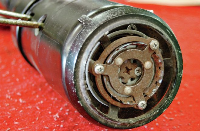
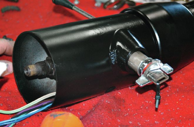
01. The steering wheel has already been removed in this photo, but this is what will greet you when you pry off the horn button. The horn contacts will have to be removed, as well as taking out the star screw and the two screws that hold it in place, all fairly easy screwdriver work.
02. After removing the upper horn contact, star screw, locking lever, and other assorted goodies, we used a steering wheel puller to remove the hub from the steering shaft. Note the pale plastic C-ring retainer in the background, which gave up the ghost during disassembly.
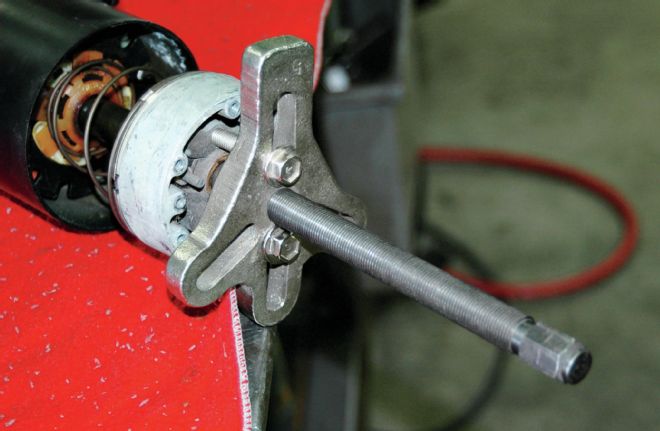
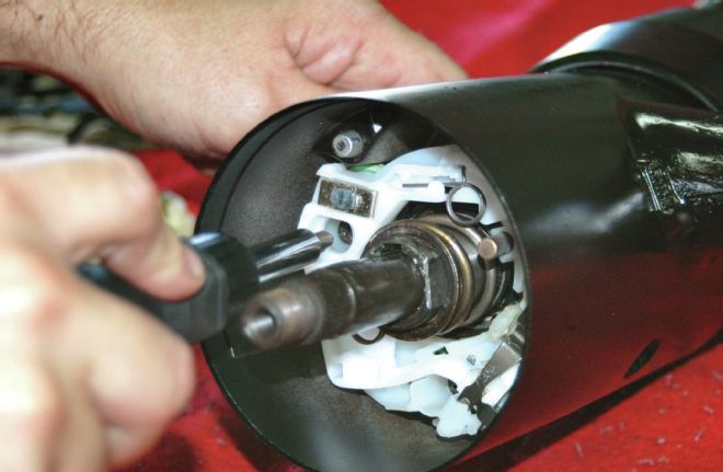
03. Called Tool J-23653 in the service manual, this tool is used to compress the spring that pushes the toothed lock ring up against its C-shaped retainer so the retainer can be removed from the steering shaft and the lock ring slid forward and off.
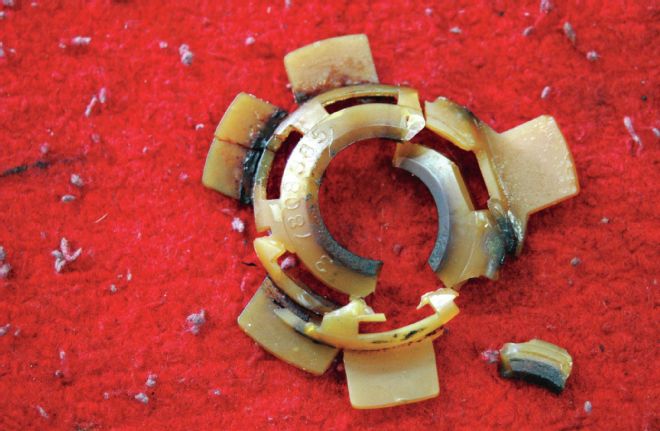
04. The plastic C-ring retainer covers the retainer that keeps the toothed lock plate in place. Ours turned out to be hopelessly fragile: this is the way it came out, to be replaced by a new one.
05. The locking ring seated on the plastic horn contact carrier, which slips into place in front of the turn signal switch. Once we removed this, we could unscrew the old turn signal switch and carefully remove its wiring from where it passes through the turn signal housing.
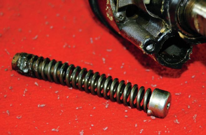
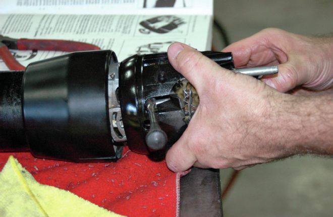
06. Once the turn signal housing was removed from the column, we started on the bearing housing, which requires removing the tilt lever spring. It’s held in place in the bearing housing by its cap. Compress it with a screwdriver and turn to free the locking tabs from their slots, so the retainer and spring can come forward out of the housing.
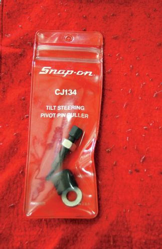
07. To free the bearing housing on a tilt/telescoping column, you’ll need a pivot pin puller to remove the pivot pins without tearing things up. Called Tool J-21854-1 in the assembly manual, we sourced this one from Snap-on.
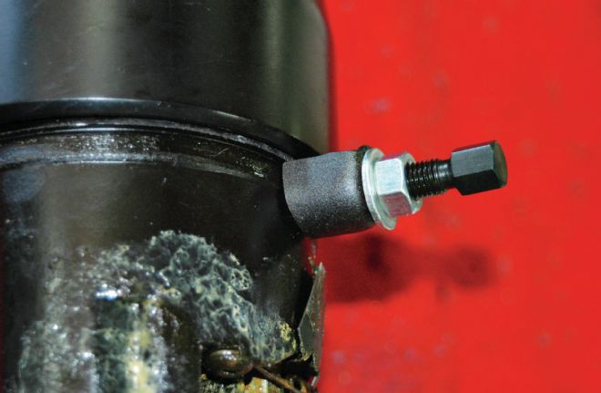
08. The pivot pin puller installed and doing its magic. Once the bolt is screwed into the pivot pin, tightening the nut uses the bolt to draw the tightly fit pin out of its seat.
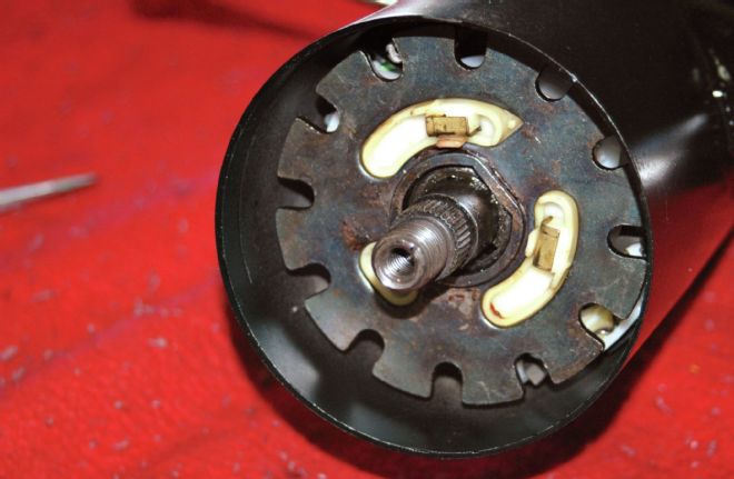
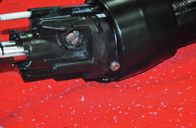
09. Here’s the bearing housing after being freed from the rest of the column. Among other things, this assembly contains the linkage required to make the ignition switch work.
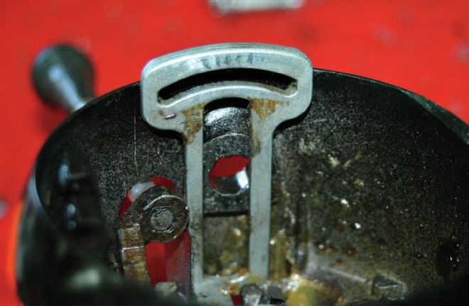
10. The ignition switch rack, seated in place in the bearing housing. This end connects to the ignition switch rod, while the other end mates with the sector gear that rotates when the ignition key is turned.
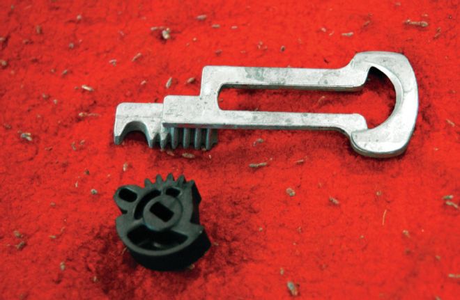
11. The new ignition switch rack and sector gear that came with our rebuild kit. The slot in the sector gear turns with the ignition lock cylinder. When the key is turned, it rotates the gear, which then moves the rack, which moves the rod that turns on the ignition switch.
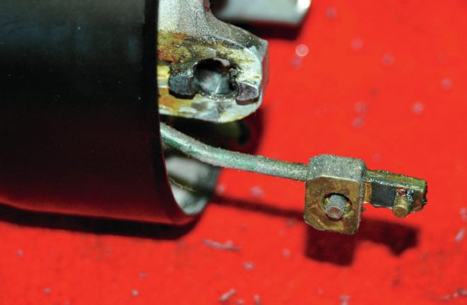
12. The ignition switch rod protruding from the turn signal housing. It connects the ignition lock cylinder with the switch itself, which is located lower on the column. The stud on the end of the rod has to be seated in the slot on the end of the ignition switch rack.
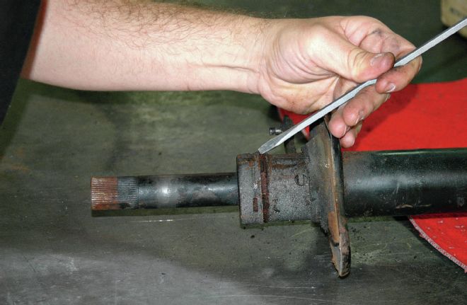
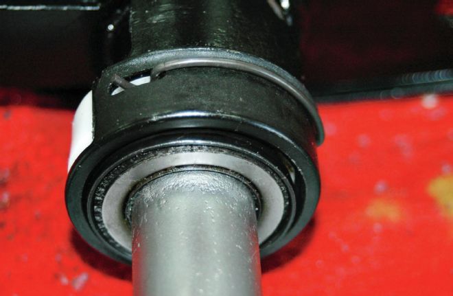
13. With the top half of the column apart, we moved to the bottom, and started by removing the lower bearing adapter so the steering shaft/jacket can be removed and the bearings replaced. The inner race of the bearing was frozen to the jacket and required more than a little force to get it off so the shaft assembly could be removed.
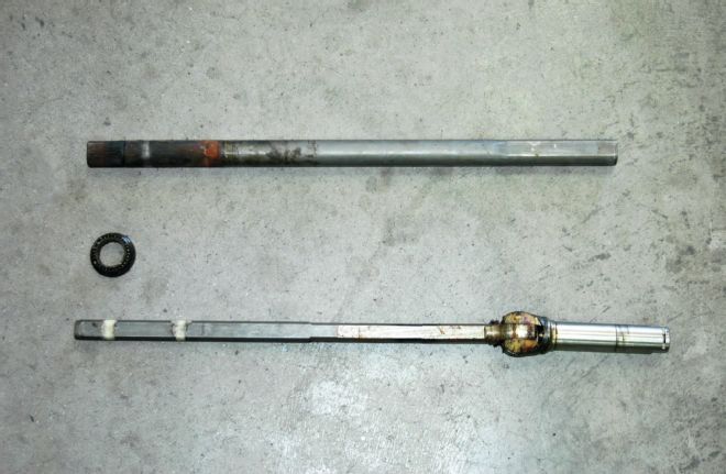
14. All Corvettes of Scarlett’s vintage came with energy absorbing steering columns that have a steering shaft (bottom) that can collapse into a jacket (top), and is held in place by the white plastic rivets visible on the shaft in the left side of the photo. Since there’s a good chance these rivets may be damaged during disassembly (ours were), it’s wise to have new ones on hand when starting the job.
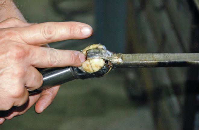
15. Greasing the steering shaft joint prior to reassembly. Called the “centering spheres,” this part of the column functions much like a universal joint between the upper and lower steering shafts to let the tilt function work while still allowing the steering shaft to turn.
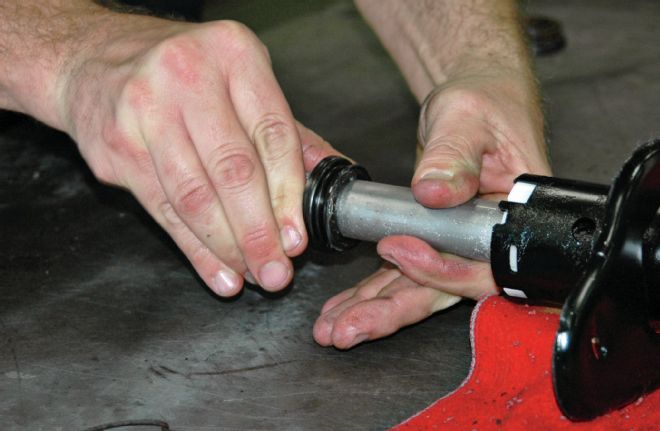
16. Installing a new lower bearing on the steering jacket, which, along with the rest of the column, has been blasted and painted. Note also the white plastic bearing adapter, which will need to be in place before the bearing goes on.
17. The lower bearing in place, with the bearing reinforcement slid in place behind it and clipped into position.
18. Seating the bearing housing back into the column. Note the slot in the ignition switch rack. This has to stay oriented with the end of the ignition switch rod, or nothing happens when the key is turned … if it goes together at all.
19. The bearing housing being installed. Note the pivot pins, which are driven back into place with a ball peen hammer and drift.
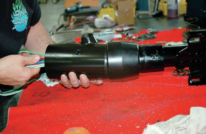
20. Once the bearing housing is back in place, the turn signal housing can slip over it. Before installing the turn signal switch, the wires have to be routed carefully through the housing. Wrapping them in tape or something comparable is recommended.
21. This is also when the key switch goes back into place. Make sure the ignition buzzer switch is properly installed, as it’ll need to be in place before the key switch is seated.
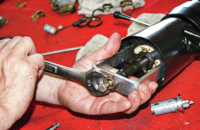
22. Screwing the new turn signal switch in place. Once you’re to the point where you can turn the steering shaft, install the turn signal lever and check to make sure that the switch works both ways and that it cancels when the shaft is turned.
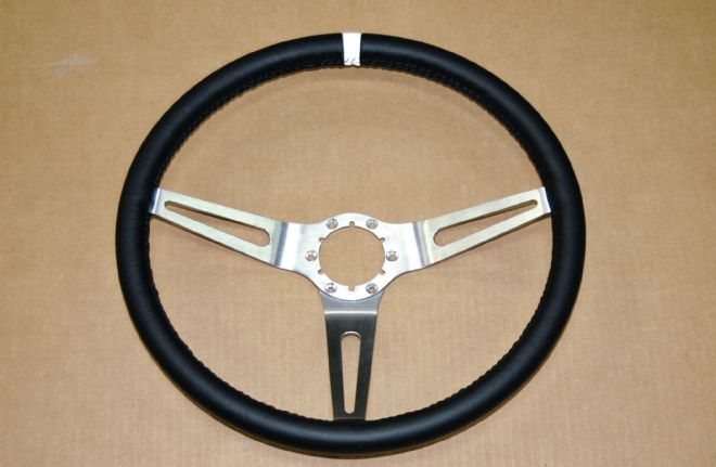
23. The visible part of the job is our newly leather-wrapped steering wheel, which was redone by Chuck Pelton. Since Scarlett is destined for the track, we had a contrasting strip of white leather sewn into place as a “straight-ahead” band, which can be useful for high-speed cornering.
Catch up on the rest of Project Scarlett's builds here:
1972 Chevrolet Corvette Scarlett Project Car - LS3 416 Installation
1972 Chevrolet Corvette Scarlett Project Car - Sidepipe Install
1972 Chevrolet Corvette Scarlett Project Car - Six-Speed Manual
1972 Chevrolet Corvette Scarlett Project Car - EFI Fuel System
1972 Chevrolet Corvette Scarlett Project Car - Cooling System and Hydroboost
1972 Corvette Scarlett Project Car - Vintage Air Gen 4 Underhood Components, Part 1
1972 Corvette Scarlett Project Car - Vintage Air Gen 4 Underhood Components, Part 2
1972 Corvette Scarlett Project Car - Replacing the Factory Wiring Harness
1972 Corvette Scarlett Project Car - Dash and Gauge Installation
1972 Corvette Scarlett Project Car - Dash Wiring Harness Installation
1972 Corvette Scarlett Project Car - Dash Prep and Radio Installation