Getting any project to the rolling and steering stage is always a milestone, and with the addition of steering in this installment of our F-100, we’ve reached that point. Our stock chassis benefits from an Art Morrison Enterprises independent front suspension, with a power steering rack, and with carefully selected parts from Flaming River, the mechanical side of the steering is now complete (we still have to add a power steering pump to complete the system).
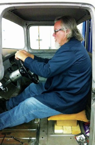
While it’s not shown in the pictures, the first item on the agenda when installing steering is to measure the desired length of the column. We were lucky in that a co-worker had a column he’d yet to install, so we temporarily mounted it on a 6-inch column drop and mocked up a seat to determine where we wanted the steering wheel to be. Not only did we determine the drop was too severe (a 4-inch would work better for us), but our column would benefit from being a couple inches shorter. Ideally the lower end of the column should protrude from the firewall a couple inches, enough to attach a universal joint.
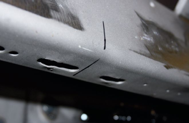
01 The underside of our F-100’s dash had these two slots that secured the stock steering column drop. We temporarily used them to fasten the column drop, but will likely weld them up and drill dedicated holes later. The reference mark denotes the center of the dash, and our desired column position.
02 A co-worker had a Flaming River 6-inch column drop and steering column which we borrowed for mock-up.
03 Mocking up the column proved useful, as it made us realize we needed a 4-inch drop, not a 6-inch, the steering wheel being too low with the latter.
04 We opted for Flaming River’s powdercoated finish, on both the column drop and the column itself. Here the drop is bolted in place, centered on the reference mark.
05 The column (masked to prevent scratching until its final location is determined) was clamped in the column drop, with magnetic vise-jaw protectors used as a temporary lower brace. Note the column, as well as the clutch and brake pedals, pass through a large hole in the F-100’s toeboard.
06 With the steering wheel (a reduced diameter tri-five Chevy item sourced through Speedway Motors) in place, it’s obvious the wheel is centered with the dash cluster.
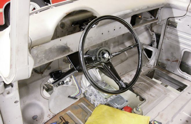
07 The tilt column at its lowest position…
08 …and again at its upper position.
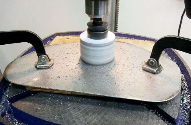
09 The hole in our floor needed filling, so we clamped a section of 14-gauge steel over the hole, marked the edge, and cut the section 1-inch larger.
10 As we now know where the steering column needed to pass through the panel, we used a hole saw to cut a large enough hole. Clamping the steel to wood meant we could drill straight through without worry.
We were very conscious of mounting our column central with regard to the dash cluster. You’re going to spend an awful lot of time behind that wheel, and if it’s off-center it’s going to bug you! So, with the wheel mounted centrally, and in a comfortable position, we could link the column to the rack. We were fortunate in that we only required three U-joints and two shafts, but if you need four and three shafts to clear headers, engine mounts, and other obstructions, so be it. Just remember that for each additional shaft, you’ll need an additional support bearing. For us, the placement of the wheel and column is critical, the routing of shafts can almost always be figured out.
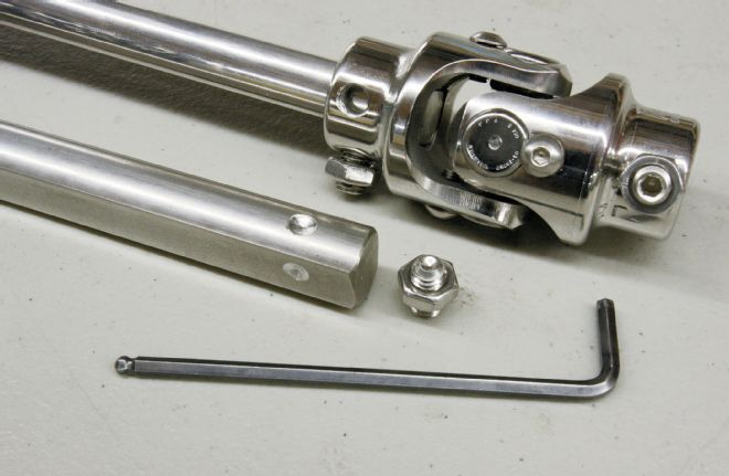
For this project we used polished stainless steel DD shafts, universal joints, and Heim joint, all from Flaming River, but mild steel versions are also available. Don’t be tempted to use cheap U-joints available at hardware stores, or intended for go-kart use or similar. The steering on your project isn’t an area to use inferior parts!
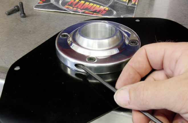
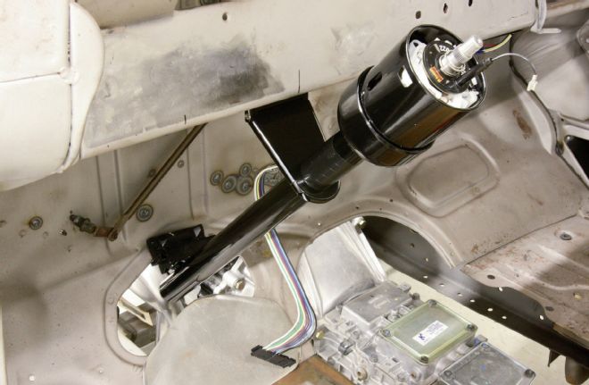
11 We used a 13⁄4-inch swivel design floor mount, bolted to the plate we’d just made and painted. This mount allows up to a 60-degree angle with a ball and collar design. On the underside of the plate we used a Floor Mount Firewall Cover.
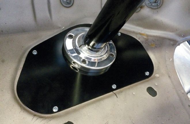
12 Once the column was clamped at the desired angle and the two halves of the Floor Mount tightened, the mounting bolts were cinched. We temporarily used self-tapping screws to secure the plate to the toeboard. It’ll get captive nuts and bolts eventually.
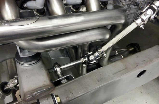
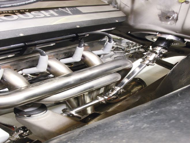
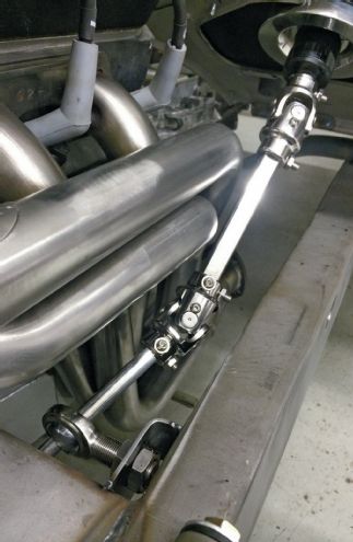
13 With the column mounted, all that remained was to link it to the steering rack. For this we’d ordered polished stainless DD shafts and stainless universal joints; a single 3⁄4-inch DD to 3⁄4-inch DD and a pair of 3⁄4-inch DD to 3⁄4-inch/36. Now to route the shafts around the header.
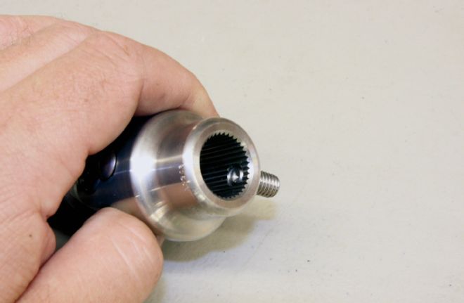
14 The 3⁄4-inch/36 has, as its name implies, a DD hole at one end, to fit the “double D” shaped shaft, and a 3⁄4-inch/36 spline at the other, to fit the 36-spline shaft on the steering rack. The U-joints all have set screws to lock the shafts in place.
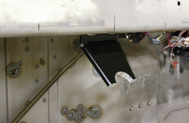
15 Here’s the 3⁄4-inch/36 U-joint in place on the steering rack shaft, with a temporary mild steel DD shaft routed under the engine mount bracket. We used the mild steel shaft to determine the length of the stainless version.
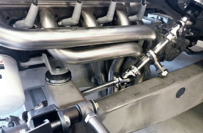
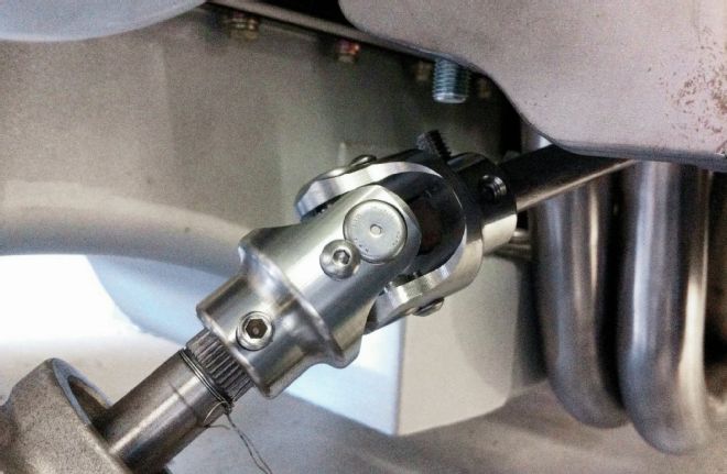
16 With the other 3⁄4-inch/36 U-joint attached to the bottom of the steering column, which is also splined, we were able to route the shafts around the header using the DD to DD U-joint. This meant we’d need a support bearing. A 3⁄4-inch stainless Heim joint had been ordered for this purpose. Now to determine whether we’d mount it on the upper or lower shaft.
17 The neatest solution was to mount it on the lower shaft, perpendicular to the chassis rail.
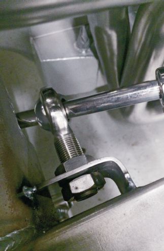
18 We fabricated this small 90-degree bracket to mount the Heim joint, welded to the chassis rail and engine mount. It seemed a neat solution and allowed access to the nut behind the bracket.
19 There are a couple of points to note here: we drilled indentations in the shaft for the set screws to seat into. This prevents the shaft from sliding out of the U-joint should the set screw work loose. Unlikely as it has a jam nut and we use thread locker, but it’s a wise precaution. Secondly, note the shaft doesn’t protrude through the U-joint to where it may cause bind during use.
20 The completed installation. The steering column exits the cabin neatly through the Floor Mount Firewall Cover, and the steering shafts clear the header, whilst being supported securely.