When it comes to lowering a classic truck, it seems that the job is divided into two camps: the simple and the difficult. Trucks equipped with an independent suspension setup from the factory, such as the '67-'72 Chevy C10s, are of the simple variety. That is, the components needed to modestly lower a truck are all bolt-on. Drop spindles, springs, and shocks are all items readily available and replace their stock counterpart with no fabrication required. Other trucks, such as those equipped with either a straight axle or the long-running Ford twin I-beam design, are a different story. To really achieve a proper drop with contemporary suspension accoutrements, it's necessary to get rid of the original suspension design. That usually means that anything that bolts to the chassis forward of the firewall needs to be binned, including the crossmember. This results in a lowering job that is much more difficult, with a bit of talent required, i.e. fabrication and welding skills.
There is a silver lining, however, in that once the job is done, not only will you have a lower-riding truck on your hands, but if you use a kit from a company like Fatman Fabrication, you'll have a truck that rides, stops, and steers better than anything that left the factory that same decade.
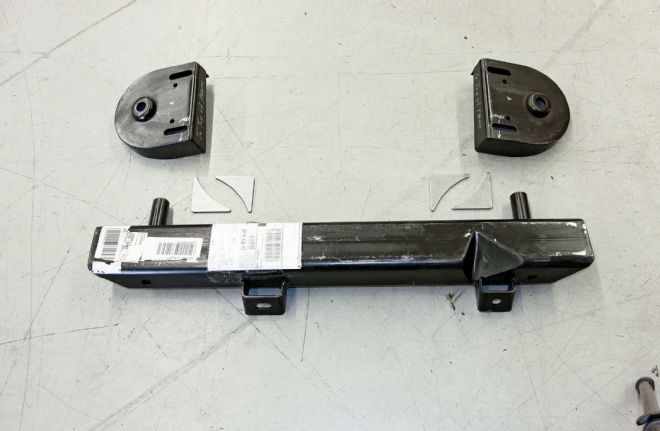
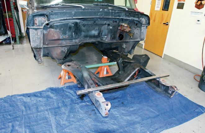
01 Here are the new Fatman Fabrications chassis components. The new crossmember replaces the stock unit and locates the lower control arms and rack-and-pinion, while the shock towers will locate the upper shock and coil spring mounts as well as the upper control arms. Four gusset plates will be used to strengthen the shock towers.
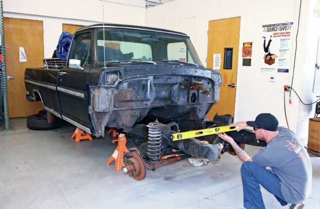
02 Arguably the most important part of the entire install is the proper setup of the chassis before we even get started. Since we'll be removing the stock suspension components, if we don't set up some baseline measurements before we get going, things will go downhill fast. First, the truck is lifted and set on jackstands, installed at all four corners. Next, the chassis is checked for level, side to side, with the corresponding jackstand shimmed if needed. It's a good idea to check for level at more than one location as well to make sure the frame isn't twisted.
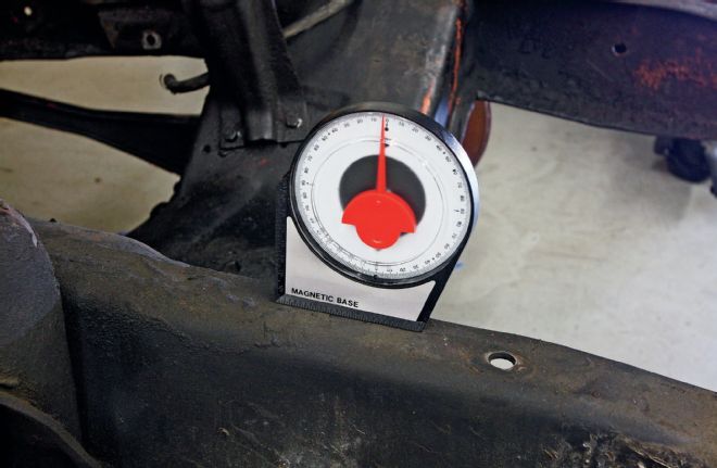
03 A 2-3 degree forward rake is more or less industry standard spec, so we set up the chassis to reflect this measurement as well before we get started.
04 The next step is to mark the axle centerlines. I use a string and plumb bob to mark the location on the shop floor. I also like to take the time to mark the rear axle centerline as well. This allows me to measure the wheelbase to be sure our plumb bob specs are within factory parameters (131 inches for a longbed). Once the axle centerlines are marked and everything looks good, the front suspension components can be removed.
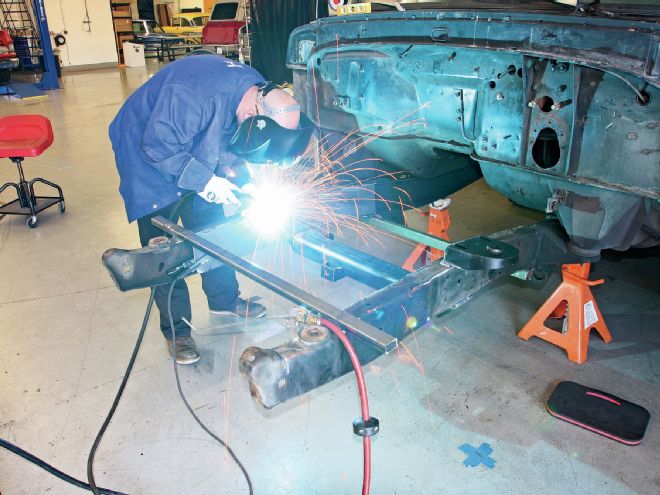
05 The last bit of preparation necessary before we get started is to tack weld a few pieces of stiff steel tubing or angle iron across the framerails. This will ensure that the 'rails don't twist, rise, or dip out of level when the crossmember is cut free and the new crossmember is welded in place.
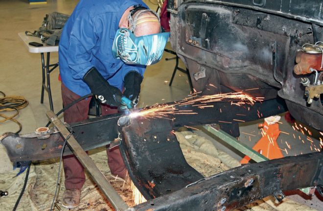
06 Now it's time for the fun bit! Using our trusty Miller 625 Spectrum X-Treme plasma cutter, I set off trimming the fat away from our Ford chassis. If your truck is as greasy as ours, do yourself and anyone within a country mile a favor and grab a couple fans to blow the offending smoke out the door. I also like to keep an air hose with a blower attached nearby to help extinguish any small fires that might erupt (they will!).
07 The stock Ford truck frame, while plenty strong, isn't exactly stiff. This is one of those frames that can really benefit from a boxing job and that's exactly what we're going to do. I picked up two 36x12-inch sheets of 1⁄4-inch steel to do the job. I clamped each to the corresponding framerail before tracing the shape onto the plate.
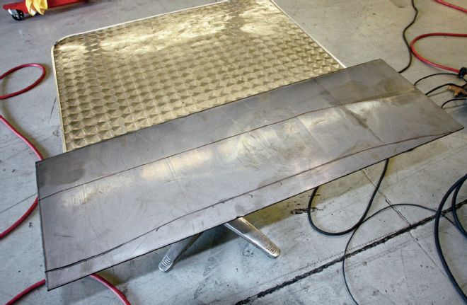
08 While 1⁄4-inch is a bit overkill for boxing plates, I had the ability to cut it and that's what the metal yard had in the remnant pile, though 1⁄8- or 3⁄16-inch plate would be fine. Here's the traced pattern, ready to be cut with the plasma.
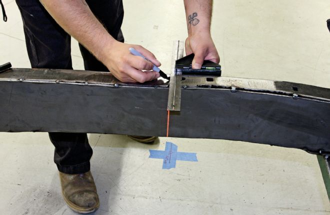
09 With the boxing plates cut out and tacked in place, it's time to mark the axle centerline on the chassis. When aligned with the two axle centerline marks on the shop floor, a laser level projects a vertical line that makes marking the axle centerline on the framerail a piece of cake.
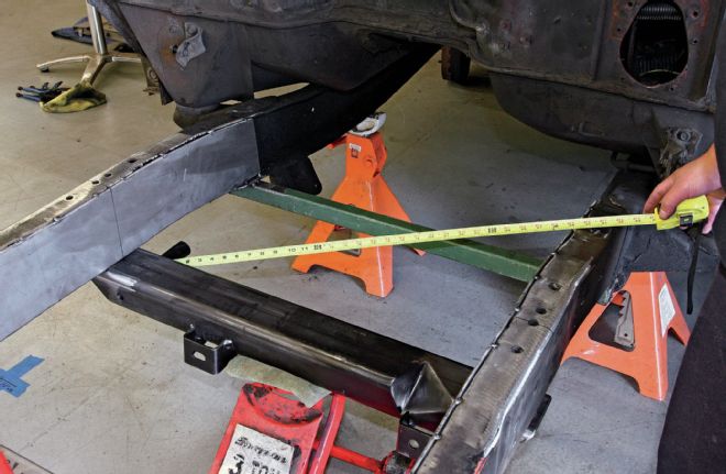
10 With the framerail marked, the new crossmember can be lifted into place and centered in the chassis. The axle centerline corresponds with the center of the crossmember. I like to measure five times and cut once, so here I'm taking diagonal measurements to ensure that the crossmember is nice and square before I tack it to the framerails.
We've made a few upgrades in the past on our buddy Danny Valenzuela's '69 Ford F-100 and one thing he always bugged us about was lowering his stock longbed hauler. Knowing that bolting on a pair of lowered I-beam axles wouldn't result in the contemporary suspension geometry that he desired, we opted to contact Brent VanDervort at the aforementioned Fatman Fabrication. What Brent recommended was their Mustang II-based IFS kit that would not only get rid of those heavy, swingin' I-beams, but it would also upgrade the stock drum brakes to disc (though in our case we had already installed a set on the original I-beams).
Though it does take some fabrication skills to install a Fatman Mustang II kit in a '65-'79 Ford truck, the majority of the modifications can be done in a day with a simple MIG welder and a 4-inch grinder. We'll be using a Millermatic 211 for all the welding requirements on this install, coupled with their Spectrum 625 X-Treme plasma cutter. If you've never used a plasma cutter before, it makes tasks such as this truly a breeze.
Bumpsteer:
An uncommanded toe change caused by suspension travel.
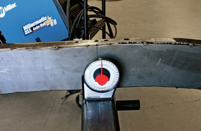
11 Since the chassis is set up at the approximate final rake, the crossmember can be plus or minus 1 degree of level. I opted to shim the back of the crossmember just a touch to get it closer to level as the bottom of the frame curves slightly downward toward the front of the truck.
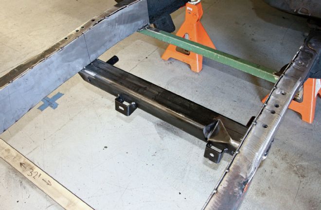
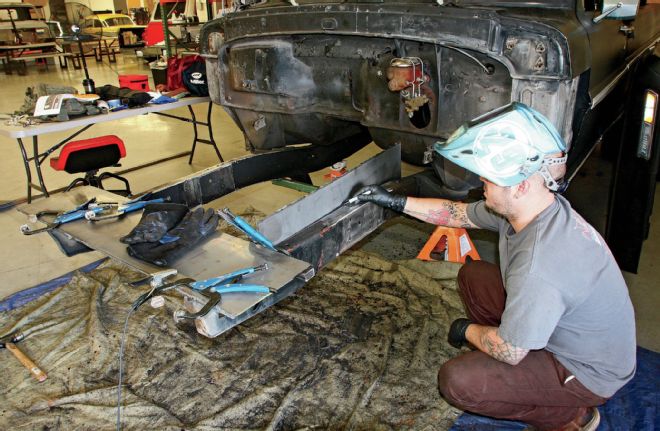
12 With everything triple checked, I tacked it into place. Note that the boxing plates haven't been fully welded at this point. I decided to wait until the crossmember was in place before putting too much heat to the chassis, just in case it decided to twist or get out shape.
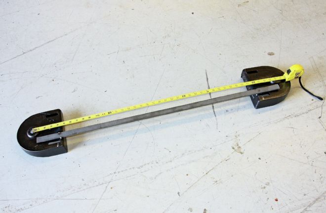
13 Next, it's time to install the shock towers. These need to be installed exactly 40 inches apart, as measured at the shock mounting holes. A piece of steel is used to retain the distance, tacked to each tower. It's important to also ensure that they are nice and even in relation to each other as well since they'll be installed on the chassis exactly as they sit.
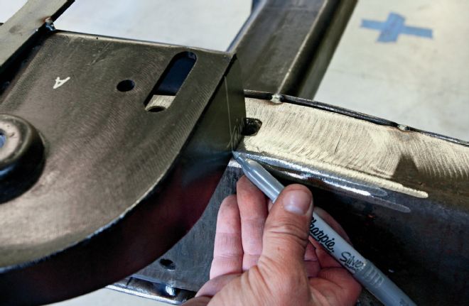
14 Since frame widths can vary, the rear corner of each shock tower needs to be trimmed so that they can fit over the framerail perfectly. Before I placed the shock towers onto the chassis, I marked the center of each, which corresponds with the shock mounting hole. When the shock towers are trimmed and placed on top of the framerail, the alignment of the centerline mark on the bottom of the shock tower and the centerline mark on the framerail will ensure that the built-in anti-dive angle of the shock tower is retained, placing the shock hole centerline slightly rearward.
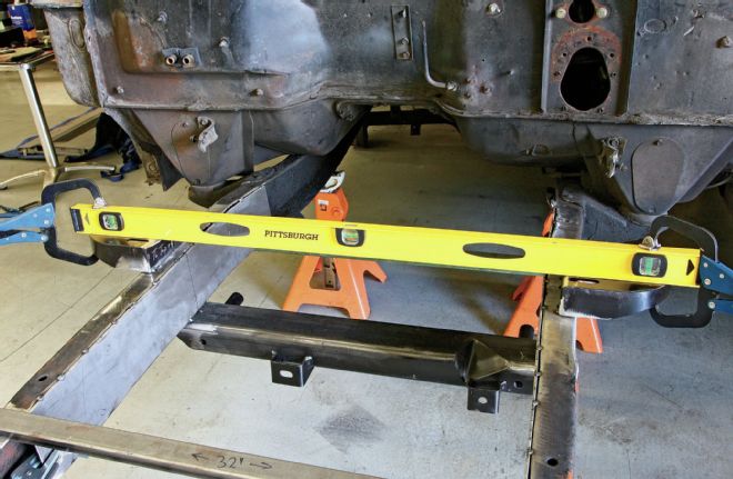
15 I first tacked the bottom edge of each shock tower to the top of the framerail before removing the jig that we installed a few steps back. Then I used a 4-foot level to ensure that the shock towers were perfectly level before tacking the sides of each shock tower as well.
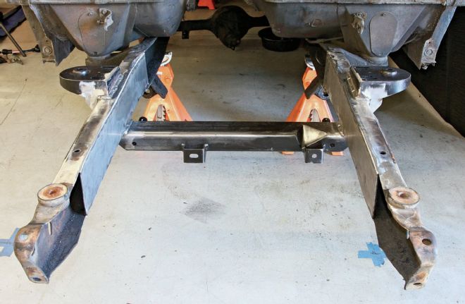
16 After an hour or three of welding and grinding, we're almost ready to start bolting on suspension components. Note the absence of those two pieces of tubing tacked to the frame at this point as well as the gussets I added to the bottom of the shock tower.
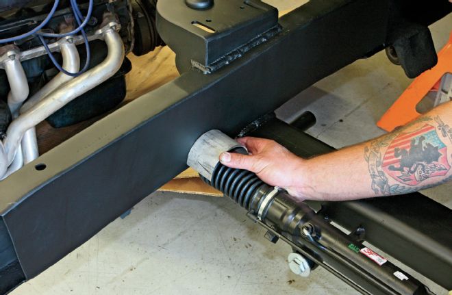
17 I hit the chassis with a coat of flat black as I thought we were done with the fab work, but I forgot one important step; the framerail C-notches for the rack-and-pinion steering. These are necessary in order to give clearance to the rack-and-pinion steering on lowered setups such as ours.
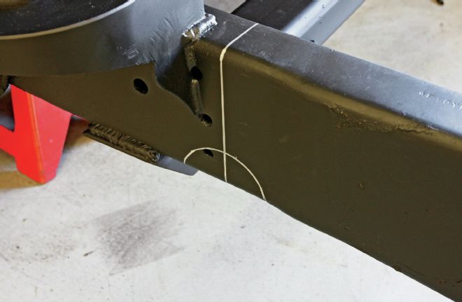
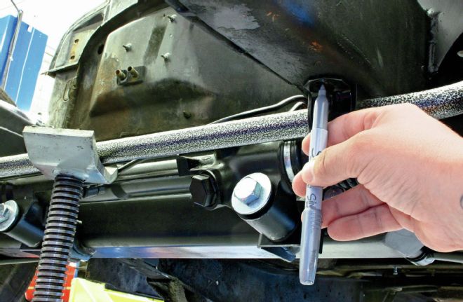
18 First, the steering centerline is determined with the rack-and-pinion installed on the crossmember. Then, the shape of the provided C-notch is traced onto both sides of each framerail so that it can be cut out using a plasma cutter.
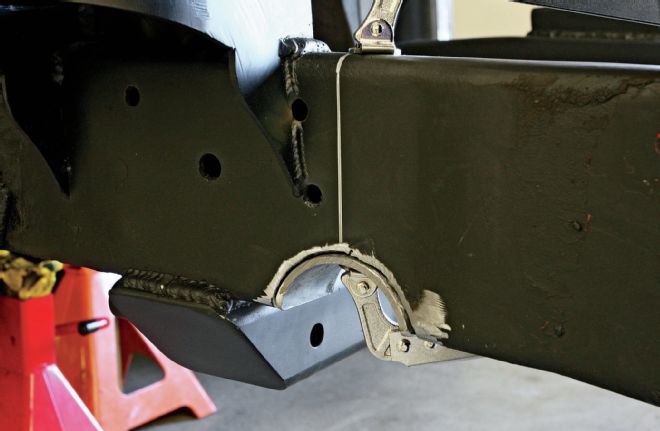
19 With the steel trimmed away, the C-notch can be clamped in place and welded up.
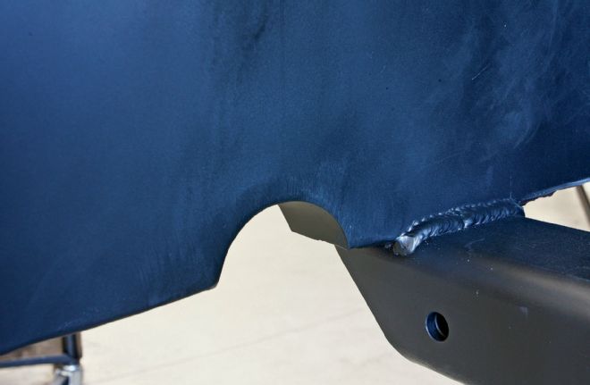
20 A few minutes cleanup with a grinder leaves the C-notch area looking nice and clean. At this point, we're ready to start bolting up those new suspension components.
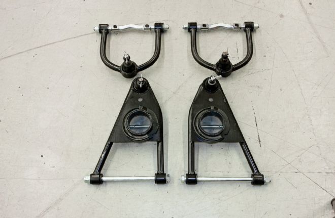
21 The control arms for the Fatman Stage II kit are tubular items fabricated from SAE 1018 steel and feature NASCAR-type screw-in ball joints and polyurethane bushings that are graphite impregnated which prevents the need for further lubrication.
22 We opted to upgrade to Fatman's Mustang II-based spindles with a 2-inch drop for our Stage II kit.
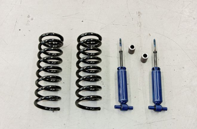
23 Shocks are over-the-counter gas-type units, shown with the shock spacers that will serve to establish ride height during the build phase of our project. The coil springs on the left are spec'd for the weight of our truck as well as the ride height desired.
When it came time to select the components for our newly dropped F-100, we opted to go with Fatman's Stage II kit. This kit is based on the specs of the venerable Mustang II IFS with a few concessions added to make it a bit more contemporary, the most important being the elimination of the stock Mustang II strut rod which attached to the lower control arm. Instead, Fatman has designed a lower control arm that straddles the front crossmember for increased stability and packaging. In addition to the upper and lower SAE 1018 steel tubular control arms, the Stage II kit comes equipped as standard with coil springs and gas shocks, spindles, and iron disc brakes. We opted to add to the package a power rack-and-pinion as well as 2-inch drop spindles. Combined with the 3-inch drop that is built into the crossmember and 1-inch drop from the coil springs, that will give us a full 6-inch drop up front, getting our Ford nice and low. A Classic Performance Products (CPP) brake system featuring drilled and slotted rotors was selected as an upgrade, as well as a sway bar to control understeer and body roll.
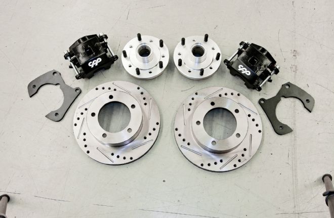
24 Fatman offers a number of brake kits, from the basic iron unit to six-piston, 16-inch rotor setups, based on the customer's preference. We opted to go with a name we've come to trust over the years, Classic Performance Products. Their kit includes aluminum hubs in the original 5x51⁄2-inch bolt pattern (other patterns are also available), matching 11-inch drilled and slotted rotors, loaded calipers, and caliper brackets. Not shown, but also provided, are the bearings, seals, hoses, hardware, and dust caps.
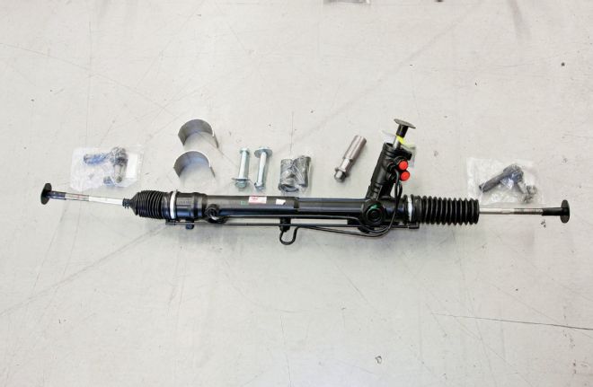
25 For our big Ford truck, we thought upgrading the stock manual steering box to a power rack-and-pinion would be a smart and comfortable move. Pictured is everything necessary to get the rack-and-pinion system installed, including the C-notches we welded in earlier and G-Tech tie rod ends. Fatman designs their IFS system with a positive caster setting of 3.5 to 4 degrees for better handling and response. This raises the steering arm on the spindle, which in turn raises the tie rod attached to the rack; the result is bumpsteer. To solve this unwanted situation, Fatman uses G-Tech tie rod ends which feature a longer tapered shaft that helps put the correct geometry back into the frontend.
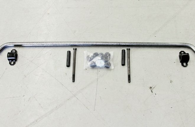
26 To increase our Ford's handling characteristics, we opted to add a sway bar to the install. Fatman control arms come equipped to accept a sway bar, so it seemed like a no brainer. The purpose of the front sway bar is to control understeer and body roll by connecting the frame to the lower control arms.
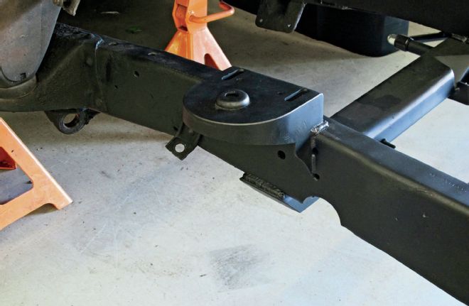
27 Here's the passenger side of our Ford chassis, ready to accept the suspension components.
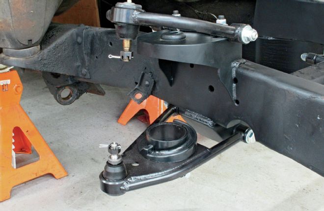
28 The first step is to install the upper and lower control arms. The upper arms are mounted so that the knurled surface of the cross shaft rests against the shock tower. This ensures that the alignment position is maintained. The lower control arm attaches to the crossmember via a single bolt, washers, and a nyloc nut. The bottom and top pivot nuts should only be tightened half a turn past the point where the washers can no longer be rotated by hand. Any tighter and excess wear, a harsher ride, and additional noise can result.
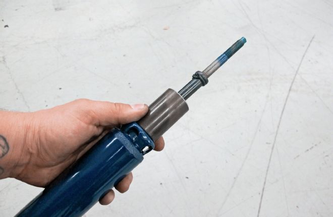
29 Here's the shock spacer installed over the shock shaft. Worth noting is the rubber stop that is present just above the spacer on the shock's shaft. This needs to be removed in order for the shock to achieve full travel on most lowered applications.
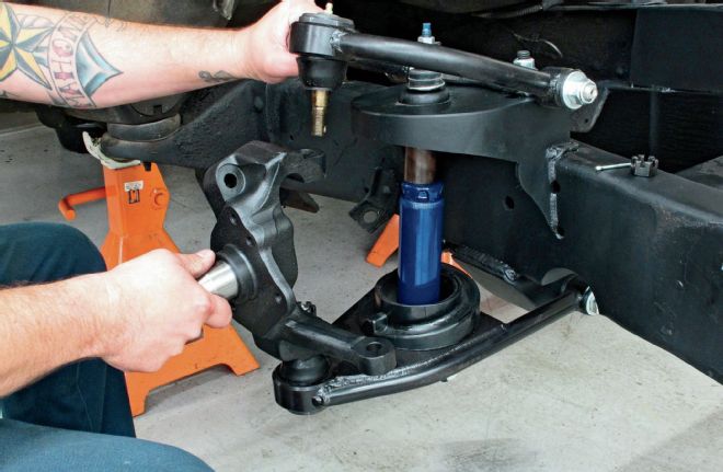
30 With the shock in place, it's time to bolt in the 2-inch drop spindle. Note the shock and spacer assembly.
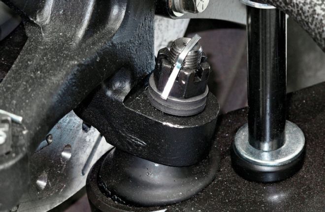
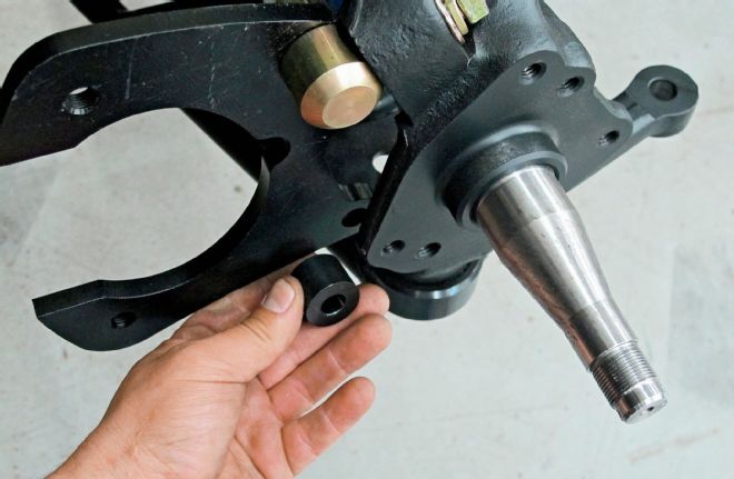
31 The lower ball joint requires the use of two spacers to ensure that the castle nut can be tightened properly and still line up with the cotter pin hole.
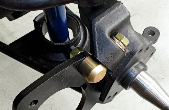
32 With the spindle in place, we can now assemble the brake and hub assembly, starting with the caliper bracket. Using the provided 1⁄2-inch hardware, the upper anchor is attached to the upper brake boss on the spindle followed by the bracket.
33 Next, the lower spacer is installed, followed by a 7⁄16-inch fastener that mates the bracket to the spindle. The upper 1⁄2-inch fasteners are then torqued to 119 lb-ft, while the 7⁄16-inch lower fastener is snugged down to 78 lb-ft.
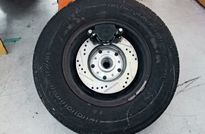
34 Before the hub/rotor/caliper assembly is installed, it's a good idea to check for fitment inside the wheel that's to be used, especially if you're using an OEM steel wheel as they can sometimes be problematic since they were designed for drum brake applications.
35 Here's the aluminum hub, inner and outer bearings, and seal. Note the dual bolt pattern on the hub, we're using the Ford 5x5 1⁄2-inch pattern, but CPP provides the option of using the same hub for a 5x5-inch pattern as well.
Installation of the suspension components is pretty straightforward for anyone who has ever worked on an IFS system before, but there are a few things worth pointing out. Fitting the coil springs with the frame bare can be a bit of a challenge, so Fatman ships a pair of shock spacers with every coil spring-equipped IFS kit. These are slipped over the shaft of each shock and rest between the shock body and upper shock tower to mimic proper ride height during the remainder of the build process. Once the drivetrain is installed, the spacers can be removed and the coil springs can be installed easily and safely without the use of a coil spring compressor. Another item that will need to be addressed is the provided 4-inch rack extension that needs to be installed on the Mustang II rack-and-pinion. Due to the wider track width of the Ford trucks than the Mustang II, this is necessary to provide the proper geometry and avoid bumpsteer.
We had the suspension components installed in a day and no sooner had the truck back together up front before we were taking stuff apart out back. We'll continue the story of slamming our F-100 next month when we cover the 9-inch Ford rearend rebuild followed by the leaf spring flip kit install, but for now, check out what it took to go from a twin I-beam to a trick IFS.
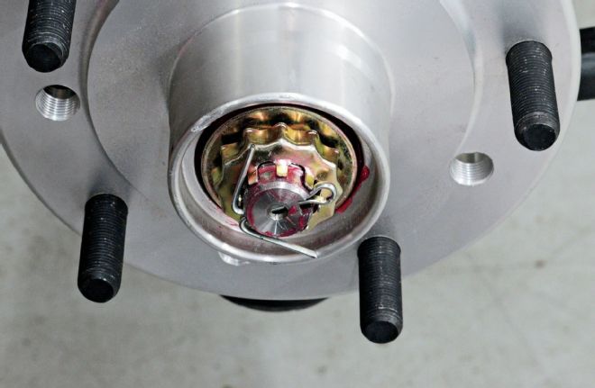
36 Once the inner bearing is packed with high-temp grease, it can be installed on the hub, followed by the seal. A wooden 2x4, a mallet, and a little care make quick work of driving the seal in place. With the hub slid onto the spindle and the outer bearing and washer in place, the spindle nut needs to be tightened no more than 12 lb-ft to ensure that the bearings are seated. With the spindle nut tightened, the hub is spun and the nut rechecked for tension. If it's still tight, the bearings are properly seated and the tension on the nut relieved. The nut is then hand tightened and the nut cage and cotter pin installed. A wrench is not needed for final spindle nut adjustment!
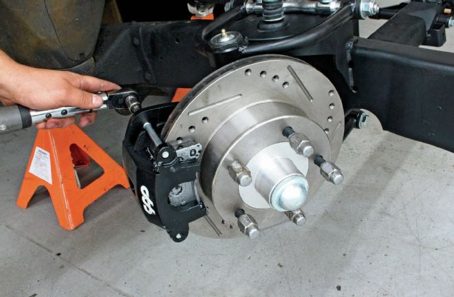
37 The next step is to install the rotors and calipers. I've had disc brake setups squeal in the past, so now I tend to err on the side of caution, liberally applying a thin coat of antiseize to the brake pads where they contact the caliper pucks. This prevents that nasty squeal noise that oftentimes is the result of the pads vibrating or oscillating against the caliper and/or puck when the brakes are applied. The rotor is installed by simply sliding it over the hub, followed by the brake caliper (bleeder screw at the top), which attaches to the caliper bracket we installed earlier. These calipers are of the "floating" type; the mounting hardware attaches to the caliper bracket and the caliper is free to float side to side ever so slightly, aiding in proper alignment with the rotor and preventing any shimming from being necessary. The caliper mounting bolts will be torqued to 35 lb-ft.
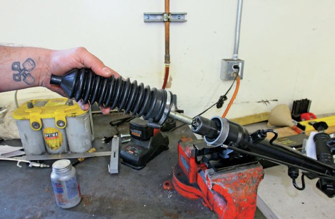
38 Our Ford truck features a track width that is approximately 601⁄2-inches, hub to hub. Since the standard Mustang II rack is 57 inches, Fatman provides a 4-inch rack extension that needs to be installed. This is necessary since simply adding longer tie rod ends would disrupt the IFS geometry, causing bumpsteer. The first step is to remove the rubber insulator boot from the rack.
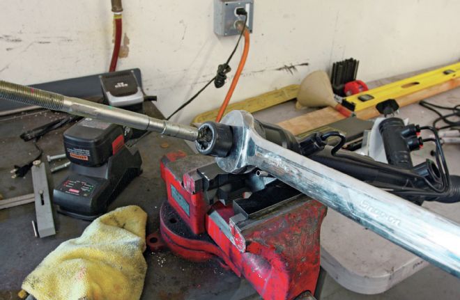
39 This exposes the inner tie rod end, which needs to be removed. The inner tie rod end is RH thread and is usually held together with some sort of mega-Loctite, requiring a big wrench to get it loose. If you can't get it loose, ask a few buddies to come by to check it out. One of them will not leave until they prove their manhood by removing it, doing the job for you!

40 The process is then reversed using the provided 4-inch rack extension spacer and a few dabs of Loctite.
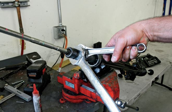
41 The original inner tie rod socket is then installed onto the rack extension, held in place ad infinitum via Loctite and a jam nut installed on the rack extension.
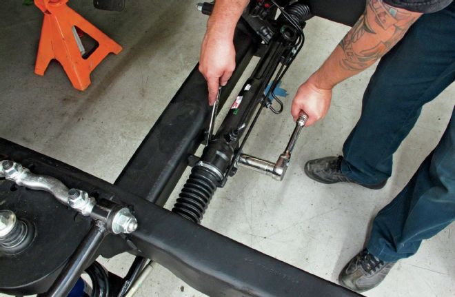
42 The rubber insulator boot is reinstalled to protect the internals of the rack and it's time to bolt the unit into place and mate the outer tie rod ends to the spindles. I typically set up a new frontend with 1⁄8-inch toe in.
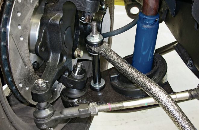
43 The last piece of the puzzle is to install the sway bar. First, the bar is installed, attached to each lower control arm via the sway bar link. Which, in our case, is a long fastener and a handful of rubber bushings.
44 Next, the sway bar is pulled up against the bottom of the frame and the saddle strap mounting holes are marked and drilled.
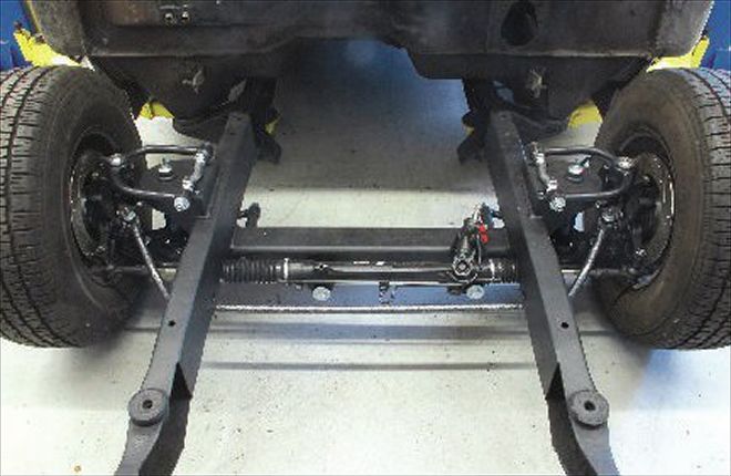
45 With everything fastened down, our Fatman IFS setup is ready to roll, pun intended!