Voodoo doesn't normally come into play when building a car up from a pile of parts, but understanding certain truths about the process of scratch-building engine and transmission mounts for a project can sometimes seem like some sort of magic.
As you might surmise, the engine and trans combo should typically be centrally located between the frame-rails and, if you can get away with it, mounted farther back from the front to aid the vehicle's handling characteristics. If you're a fan of certain Chrysler products, you'll note they will sometimes offset an engine so steering can clear the headers or some other obstruction, but, for the most part, you want to aim at getting the engine centrally located.
The trick you don't hear about too often is the angle of the driveshaft and its relation to the transmission's output shaft as well as the pinion shaft of the rearend-a concept usually referred to as "pinion angle." If you're starting with a bare chassis, you can either begin up front with the engine/trans combo (already bolted together) or at the rearend. Typically a rearend is supported either by a leaf-spring system or a coilover design that incorporates a triangulated or parallel four-link. With four-bar setups, either one or both sets of bars are adjustable so you can dial in the pinion angle that way (just make sure to adjust it the same on both driver and passenger sides). A leaf-spring system reacts differently under load than a four-bar type, but the concept for determining pinion angle is the same.
What you should know first is that for U-joints to work correctly, they need a little side pressure for the grease to lube their needle bearings. If they're installed in line with each other (when there is zero degrees difference between the angle of the trans tailshaft and pinion shaft), a vibration may occur in the driveshaft at certain speeds, plus the U-joints will wear out faster. This will also happen if the angle between the transmission's output shaft and the pinion shaft is too great.
In most street-driven applications, it's common to dial in the driveshaft angle at three degrees, with one end having the opposite angle of the other (the pinion shaft usually points up while the transmission output shaft points down the same amount). One school of thought believes an angle of 10 or more degrees at the pinion shaft will produce better traction in vehicles with high horsepower, but nearly every street-driven application should use the three-degree measurement.
If you're starting with a bare chassis, every part involved (engine, transmission, and rearend) can be adjusted as you begin the assembly. Though it's better to have every component on the car to simulate its eventual operating condition (body completely assembled, interior in, wheels on and inflated to the right pressure, etc.) you can get close with less.
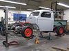
The California Hauler, a '41 Willys truck we acquired through Auto Classics, is set up on an S-10 chassis that already had the rearend and its stock rear leaf-spring suspension installed by the factory. All we wanted to do was install the engine and transmission, so we simply needed to check and measure the angle at the rearend's pinion shaft and invert that number when locating the engine and trans combo. (If the pinion shaft is at three degrees upward angle, then the transmission output shaft should point downward three degrees.)
We delivered our chassis to Dagel's Street Rods in Orange, California, to have custom engine and transmission mounts made. Dagel's is a full-service shop that not only retails all sorts of products, but also manufactures and fabricates many useful parts. Shop owner Gary Dagel was to design the mounts, but first had to dial in the truck's correct pinion angle. He started by measuring the pinion shaft angle, and observed a reading of zero degrees (in other words: parallel to the ground).
There are manufacturers (usually found in the off-road market) that make small wedges that can be inserted between the spring pad and the leaf springs, which effectively rotate the housing a few degrees and thereby change the pinion angle the same amount. We'll look into getting a set of those before the Hauler gets on the road, but for now all we need is "close."
With the pinion angle found, we then set the engine and trans combo in place, paying attention to locate the tailshaft in the middle of the cab's trans tunnel. Once Gary fabricated the trans mount crossmember and attached the transmission, he set the degree finder on the flat plane of the intake manifold and began to raise and lower the engine until it pointed downward three degrees (so the driveshaft will angle down slightly as it goes toward the back of the truck). Once we install the pad wedges that will give us the three degrees we need at the pinion shaft, the two opposite angles (three degrees upward at the pinion, three degrees downward at the trans output shaft) will cancel each other out, and the speed fluctuations that can generate vibrations in the driveshaft won't occur.
Note: Another wild card in determining what angle the engine should go into the chassis is what type of induction system you plan to use. Since fuel injection doesn't care if you're on an incline of any sort to operate, engine placement isn't that critical (except when it comes to the pinion angle). With any sort of carb setup, you have to dial in the engine's placement to more exacting standards, because the carb's float bowl needs to be level so it works correctly. (We won't even mention certain intake manifolds that are designed to have a few degrees of rake!) Setting up the engine so the carb is level during chassis construction, but then adding big 'n' little tires later defeats the science behind float bowl operation. Changing your wheels after construction won't adversely affect your pinion angle, because once the engine, trans, and rearend are set in place, the angle won't change between those parts. The best advice is to do this work when you have all the components you're going to use already installed on the vehicle.
Once Gary found the desired angle for the engine, he then made a cardboard template for the custom engine mounts and transferred the shapes to a 3/16-inch metal plate. He then tacked all the pieces together and test fit it on the chassis before doing the final welding.
With the engine and trans mount fabrication completed, we can now go about installing the Smeding 347-stroker motor (which is backed to a TCI Automotive AODE transmission) and measure for a driveshaft. In the coming months, KIT CAR will have an in-depth look at both the automatic trans and the Smeding powerplant, as well as a look around the Smeding facility to see how they build all those fantastic performance motors. After that, we'll lower the truck via lowered rear springs and front coils, install the driveshaft (paying close attention to U-joint phasing-a whole 'nother story), and then it's on to the assembly of the nose section. So stay tuned-it's getting interesting!