John Lancara Asks…
Q: I have a 327 in my '31 Ford that features nearly the same cam and components as the one you referenced recently in Pit Stop (Nov. ’12). Since a 1.6:1-ratio rocker arm will push the valve a little farther into the combustion chamber and cylinder, do I need to be concerned about possible piston-to-valve contact (especially at higher rpm)? My compression ratio is 9:1.
A: Yikes! Another one of those “it depends” questions. On an internal-combustion, four-stroke engine, the piston gets closest to the valves during the overlap period near top dead center (TDC), at the very end of the exhaust stroke and the beginning of the intake stroke. At this point, the exhaust valve is nearly closed, and the intake valve has just begun to open. When the cam approaches max lift, the piston is well down the cylinder and beyond the reach of the valves, so although a higher rocker-arm ratio increases max lift significantly at the cam centerline, there’s relatively little change in lift when the piston is near TDC. But there are lots of other variables that must be taken into consideration. Let’s lay them out.
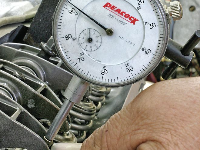
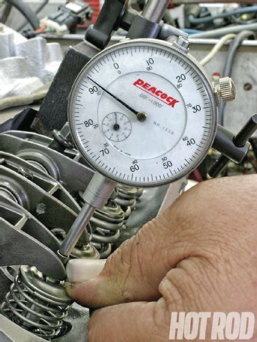 The easiest way to check PV clearance on an assembled engine is via light checking springs that permit working the rockers by hand. This GM LS-style small-block is in trouble: The stock short-block with its notchless, pure-flat-top, cast pistons had only 0.007 inch exhaust clearance when a cam with 251 degrees of duration at 0.050 and 0.624-inch valve lift was installed.
In your referenced Pit Stop letter, Francois Bougeant stated that his Ford small-block had “a cam with 276/281 degrees advertised duration and 0.471-inch valve lift.” Now on the Ford, that would be with 1.6:1 rockers, but let’s suppose your small-block Chevy’s hydraulic cam also has 0.471-inch lift with its stock 1.5:1 rocker ratio. Moving from 1.5:1 to 1.6:1 rockers increases max lift to 0.5024 inch; going all the way to 1.7:1 rockers ups the lift to 0.5338 inch. For example, with 1.7:1 rockers:
New Valve Lift = (Old Valve Lift ÷ Old Rocker Ratio) × New Rocker Ratio
= (0.471 ÷ 1.5) × 1.7 = 0.5338
Note that with a mechanical cam, the actual lift, as seen at the valve, would be minus the running valve lash.
Another way of looking at it is that moving from a 1.5:1 to a 1.6:1 or a 1.7:1 rocker arm increases valve lift by approximately 6.3 and 13.3 percent, respectively, over the entire curve from whatever the valve lift was before the change in ratio. For example, with 1.7:1 rockers:
Percent Change = (New Ratio ÷ Old Ratio) – 1
= (1.7 ÷ 1.5) – 1 = 0.133 ≈ 13.3%
However, this does not mean the PV clearance near TDC/overlap decreases by the same amount or percent as the increase in lift or rocker-ratio change. The rate of acceleration of both the cam and the piston aren’t constant, so the exact amount of any clearance change is a moving target; there are, after all, several different variables in play operating simultaneously. At the closest piston approach point to the valve, clearance can change more than 13 percent with a big cam and/or a hard-core engine originally built to tight clearances. On the other hand, it can be less than 13 percent with a mild cam and a short-block not built to tight blueprint minimums.
On steel-rod engines, most engine builders like to see 0.080 inch minimum PV clearance on the intake side and 0.100 inch on the exhaust side. The big assumption, of course, is that you know or can estimate with a reasonable degree of certitude what the PV clearance was to begin with. That leads to the fundamental question you should be asking: At what point does a cam become big enough to mandate checking PV clearance?
When discussing a given cam’s characteristics or “bigness,” most hot rodders and engine builders categorize a cam and its behavior in a motor in terms of the lobe duration at 0.050-inch tappet-lift (aka “duration at 0.050” or “0.050 duration”). A modern, aggressive hydraulic roller cam with Bougeant’s claimed advertised duration might have about 224/230 0.050 duration (in any event, it’ll be listed on the cam card). When choosing a new cam, its 0.050 tappet duration far outweighs gross valve lift in estimating the potential for PV-clearance issues.
However, there is a whole host of other factors that also weigh in (for a basic list, see sidebar on page 124). Therefore, it’s hard to come up with an ironclad, across-the-board rule for when a PV-clearance check becomes mandatory for all engines in all situations. To take one example, clearance with the same basic lobe profile will vary by engine and cylinder-head design, because the valve centerline angle and the cylinder-head deck is different with different engine families and heads, and the piston and dome design can vary as well. CP-Carrillo’s Mike Lazano points out that “the flatter the head’s valve angle, the greater the chances of interference because the valve is inherently closer to the deck. Installing larger valves also decreases clearance, because due to the valve angle, one side of the larger valve head ends up closer to the piston.” Of course, a high-dome piston will have more issues than would a pure flat-top.
But assuming a typical, production-based small-block Chevy with 23-degree valve-angle heads; generic, four-eyebrow, flat-top pistons; and a cam ground with a 110-degree lobe-separation angle (LSA), 0.050 duration in the 220s should not have a problem. Move up to the 230s, and the engine will probably be OK; at 240 you really ought to check; at 250 or more, you damn well better check. I’d start checking at 230 degrees and above—but that’s just me.
Just as the rocker ratio multiplies lift, it also slightly increases the effective duration, as seen at the valve. However, cam-duration numbers on overhead-valve engines are nearly always generated at the tappet (no rocker-ratio multiplier). For the purpose of estimating whether any rocker-ratio increase makes the cam “big” enough in terms of these 0.050-tappet-duration guidelines to warrant a PV-clearance check, Comp Cam’s Billy Godbold provides this helpful hint: “Every ½-point change in rocker-arm ratio is like increasing the effective 0.050 tappet duration about 2 degrees, and every full point is worth about 3 degrees.” That means if you jumped two points (i.e., two-tenths) in ratio from 1.5:1 to 1.7:1, Godbold says the cam will behave like it has 6 more degrees of 0.050 tappet duration. I want to reiterate, however, that the actual duration numbers at the tappet don’t really change; we’re talking only about how the cam “behaves” at the valve for the purposes of establishing PV-clearance guidlelines.
These rules of thumb assume a 110-degree LSA as the baseline norm. But the narrower the LSA ground into the cam, the greater the amount of overlap near TDC and the less its inherent PV clearance. “Every time the cam grinder moves the LSA 2 degrees narrower on an otherwise equivalent cam—from 110 to 108 degrees, for example—it’s like adding 4 degrees of 0.050 duration,” Godbold explains. The opposite also holds true: A wider LSA (more than 110 degrees) increases PV clearance.
What about advancing the installed intake centerline (something that can be changed by the end user)? Every 2 degrees the intake centerline is advanced is equivalent to adding 4 degrees of 0.050 duration in terms of its effect on PV clearance for the intake valve. But this also closes the exhaust side sooner, meaning the exhaust-lobe duration, in terms of how it effects PV clearance, ends up 4 degrees milder.
For the purposes of measuring PV clearance, the exhaust valve is generally closest to the piston at 10–15 degrees BTDC/overlap, while the intake valve is generally closest to the piston at 10–15 degrees ATDC. But there’s an exception to every rule, so you should start checking the exhaust at 20 degrees BTDC and the intake right at TDC. In each case, check every 2 degrees until clearance starts to increase. If clearance is on the margin, and the engine is not blueprinted (for example, the crank isn’t indexed and/or the rod center-to-center lengths aren’t all the same), you’ll need to check all the valves on every cylinder.
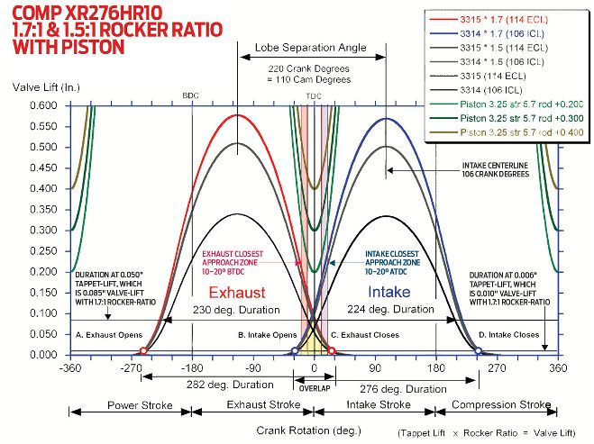
COMP XR276HR10 1.7:1 & 1.5:1 Rocker Ratio With Piston
This lobe-profile map of Comp Cams’ XR276HR Xtreme Energy hydraulic roller cam (276/282 degrees advertised, 224/230 degrees at 0.050, 0.502/0.510-inch valve-lift with 1.5:1 rockers, 110-degree LSA, 106-degree intake centerline) illustrates many of the concepts discussed here. With the cam ground 4 degrees advanced, PV clearance on the intake side is tighter than it is on the exhaust. Of particular interest is how a change in rocker ratio yields only slight valve-lift changes in the critical overlap zone. However, the piston’s distance from the valve seat (as established by a TDC drop test simulating a Chevy 327 and plugged into proprietary software that maps its position within the cylinder through the entire combustion cycle) makes a big difference: There’s ample clearance with a 0.400-inch drop (typical of production-based pistons and heads), barely sufficient clearance with a 0.200 drop and 1.5:1 rockers, and marginal clearance (less than 0.080 intake/0.100 exhaust) with a 0.200 drop and 1.7:1 rockers. To a pro engine builder, this indicates the need to check PV clearance on the actual build with a 0.300 or less drop. The valve notches could be fly-cut deeper to increase the safety margin, and/or a milder cam can be selected.
To check PV clearance on a fully assembled engine, the most common method is to substitute lightweight checking springs for the standard valvesprings, then install a dial-indicator reading off the spring retainer. If the heads are off or have to be removed, there is also the clay method: Place a lump of clay into the valve-notch area of the piston; install the head with the complete valvetrain installed and properly adjusted; roll over the engine through the overlap event; and then remove the head and measure the valves’ impression on the clay with a calipers or straightedge to determine clearance. The clay may be carefully sectioned with a razor blade to get a better view. The head gasket does not need to be in place for these tests, provided you remember to add its compressed thickness to the measured numbers.
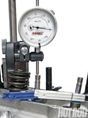 When building a brand-new engine, a valve-drop test can help the cam-grinder or piston-maker determine whether your selected cam may have PV clearance issues. No problems here: This Ford Cleveland at Westech Automotive has 0.430-inch valve-drop clearance at TDC. Clothspins work well for temporarily holding the valves in place.
If you are building a brand-new engine using custom parts, Westech Automotive’s Norm Brandes says a straight valve-drop test can be helpful in estimating its potential PV clearance. To do this test, assemble the short-block; place the head on the engine with valves installed for the cylinder to be checked but with no springs; set up a dial indicator on the valve stem; rotate the engine to 20 degrees BTDC; release the clothspin; let the valve drop free until it contacts the piston; and record the numbers. Repeat in 2-degree increments, as previously described. Some cam grinders can plug these numbers as well as the crank stroke, rod length, and piston-compression height into custom software to check if the cam will likely have a PV clearance problem on your motor. If you haven’t yet ordered your custom pistons, a similar test can also be done with the head placed on a flat surface; that will help to ensure the piston’s valve-notch depths and locations are right for your build.
In any event, apply common sense: If the valve-drop test result is less than 0.300 inch at the closest approach point, I highly recommend performing a full PV clearance test on the actual engine.
As for your engine specifically, assuming there was at least 0.300-inch actual measured PV clearance to begin with in a cam at your performance level and short-block-modification state, you’ll almost always be safe with 1.6:1 rockers, and there probably won’t be a problem with 1.7:1 rockers, either. But never say never.
Also, remember that increasing rocker ratios can affect valvespring clearances as well as overall valvetrain geometry, which will in turn affect high-rpm valvetrain stability—but that’s a topic for a whole ’nother discussion, all with its own new set of variables! Here again, common sense should hold sway: The greater the increase in rocker ratio and the more radical the cam, the more you have to watch out for all these things to avoid getting bit on the posterior.
Factors That Affect PV Clearance
Changing any of the following, individually as well as collectively, will alter your piston-to-valve clearance:
Ask Marlan a Tech Question: PITSTOP@HotRod.com