Long before electronic fuel injection or even performance Holley carburetors, high-end racers operating primarily at wide-open throttle used a purely mechanical, constant-flow fuel-injection system first pioneered by Stu Hilborn in the late '40s, a system that is still preferred today by many drag racers and Sprint Car racers, particularly those using alcohol fuels, and it's the thing to have in a retro gasser, which is hugely popular now. Even in 2010, Hilborn systems and its close relatives continue to hold sway not only in nostalgia drag cars, but also in those higher-end Sportsman and professional classes where allowed by the sanctioning body's rules. And let's not discount its visual appeal, either: The massive injection stacks poking through the hood and its badass belt- or cam-driven mechanical fuel pump practically scream that the car is a serious player. But making them work and keeping them working long-term requires regular attention, constant maintenance, and (gasp!) actually turning a wrench. Although Hilborn is specifically referenced in this article, the same basic principles apply to competitive constant-flow, mechanical systems, including the still-available Kinsler and Enderle setups, as well as the Crower units now serviced by Ron's Racing.
How Fuel Injection Works
A constant-flow fuel-injection system assumes that any engine's fuel curve requirement is nearly linear: Fuel flow to the engine should increase in direct proportion to engine rpm. This is accomplished by means of an engine-driven positive-displacement fuel pump that delivers fuel to each cylinder via individual lines and nozzles. A set of throttle butterflies regulates airflow to the engine. The greater the amount of throttle opening, the higher the airflow and engine speed. The higher the engine speed, the greater the pump output. This sounds like a pretty simple and straightforward way to deliver fuel to an engine, but there's a problem: Laid out as described, the only way to richen or lean the system is by changing the entire fuel pump size. That is a pain and compromises low-rpm fuel pressure and delivery.
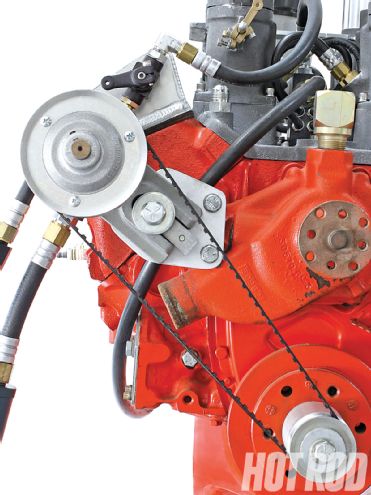 The fuel pump is driven at half the engine speed. On a beltdrive setup like this, the pump pulley will always have 32 teeth and the crank pulley will have 16 teeth. Pump, mounting bracket, and pulley kits are available for most popular engine combinations.
The solution is to use a pump with a safety margin that supplies more fuel than the engine actually needs, then meter the correct fuel amount into the cylinders by regulating the port nozzles' orifice size. This raises fuel pressure in the entire system, ensuring a constant supply at each nozzle while enhancing fuel atomization. The fuel flow at each nozzle is determined by the pressure of the fuel delivered to it, and the fuel pressure (as we've seen) increases along with engine rpm.
But what do you do about all that extra, unneeded fuel? You recycle it back to the gas tank. Hilborn's fuel pump has an inlet and an outlet side. On the outlet side there are three ports. One feeds the injectors; the other two are available to bleed off (or return) excess fuel to the tank. All systems use the second outlet, called the primary return or main bypass. It contains a restriction-known as the main jet or pill-that ensures fuel flows to the nozzles first. Pills come with different size orifices to control how much fuel is recycled. Changing the orifice size richens or leans the entire system, but it works the opposite way compared with a carburetor jet. To richen the engine you use a smaller pill because it allows less fuel back to the gas tank and consequently more for the engine. The primary bypass also contains a spring-and-poppet valve that effectively blocks off the main jet to help develop pressure during cranking when pump speed (and pressure) is very low.
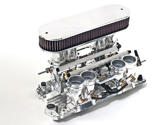
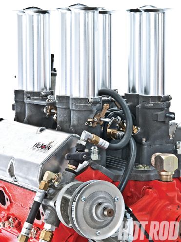 Nothing says hot rod like old-school mechanical, constant-flow fuel injection. Hilborn injection like this unit on a small-block Chevy still gets the job done in racing and looks supercool doing it.
The third outlet is for an optional high-speed bypass. Only the highest-end racing systems, usually running methanol at very high rpm, require this additional cutout. The cutout is an additional spring-loaded poppet valve that releases fuel back to the gas tank when the top-end fuel pressure is too high.
The fuel pump's outlet injector feed line runs to a common junction block, usually located in the center of the intake manifold on a V-type engine. This metering block has a large inlet port for the fuel pump line, small outlets that correspond to the engine's number of cylinders (and injector nozzles), provisions for an additional fuel tank return line called the secondary or low-speed bypass, and an internal barrel valve that functions to reduce fuel flow at idle and the first one-third of throttle opening, as well as permit adjustment of the idle fuel mixture.
The secondary bypass is spliced into the barrel valve's low-speed circuit. It was originally developed for circle track and road racing applications in which the throttle is often closed at high engine speeds when going into a turn. This cuts off airflow to the cylinders while fuel flow from the pump remains high, causing an over-rich condition. To prevent this, the spring-loaded secondary poppet valve is used that opens at a set pressure to bleed off excess fuel, but it operates only in the first one-third of throttle travel rather than on the top end. This additional bypass has proven so successful that it is now used in virtually all applications.
Typical System Layout
Here's a typical system layout for a door-slammer with a rear-mounted main fuel tank. When the fuel tank is in the back, a separate forward-mounted reservoir is highly recommended to ease priming and minimize system restrictions. With such a separate tank, an electric automotive fuel pump (1) and filter (2) feed fuel from the main tank to the surge tank through a Holley float bowl (3) that is used to regulate the tank's fuel level. The surge tank needs a vent (4), preferably exiting outside the engine compartment.
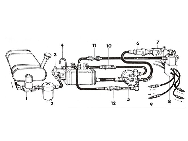
Fuel is drawn from the surge tank by an engine-driven injector pump (5), which delivers the main fuel feed to the barrel valve (8) through a high-flow inline filter (6) and shutoff valve (7).
Shopping for Fuel Injection
Constant-flow fuel injection has been around for more than 60 years. That's good and bad news: Good because there are tons of used parts available for reasonable prices on eBay, bad because 60 years of evolution has spawned many detail changes that can create parts compatibility problems for the unwary buyer who ends up with a mismatched combination. Intake manifold and nozzle design has changed over the years; many of the used parts were originally intended for use on higher-end race exotic blown fuel applications and are likely too big for use on more reasonable Sportsman or amateur-level combinations, and critical wear components like the fuel pump, even if the right size for the application, may be plain worn out.
You see, injection system manufacturers custom tailor each system they build for the specific combination. If you call Hilborn and order a new system, it wants to know the engine type, size, rpm range, compression ratio, cam, and cylinder heads; the type of racing and racing class; the fuel type; the vehicle weight and drivetrain specs; and (if blown), the percentage of blower overdrive and boost pressure. From this information, Hilborn can assemble a compatible system with the appropriate throttle bore size, barrel valve, nozzles, pump size, main jet (pill) selection, and type and setting of bypass units. Obviously, it's purely a matter of blind luck if a used system will work on your specific combo. And-whether due to wear or incompatibility-if you end up replacing major expensive parts such as the fuel pump, the barrel valve, or even the intake, it may not be such a bargain after all. Buyer beware.
Beyond just selecting the right components, new and used systems must be flowed at Hilborn or other mechanical fuel injection specialists to make sure all the parts are properly matched. Production variances, especially on older units, mean that even two supposedly identically configured systems may not flow exactly the same without custom tweaking. Although precision parts are becoming available that have more accurate flow control, you are unlikely to find them in a used system. Bottom line: Always have a used system flowed before tuning anything, and treat your matched set of jets and nozzles like gold.
Hilborns On the Street?
Hilborn mechanical-injection systems are intended strictly for racing, and the company made a very firm point of that repeatedly while we worked on this story. The company offers no tech support or assistance for using its systems on the street. Constant-flow fuel-injection is designed to work at wide-open throttle (WOT) under load above 2,500 rpm. Street engines cruise around at part-throttle, low-load conditions-and there are many different possible loads even at the same throttle angle. The barrel valve lacks the sophistication to properly meter fuel under such varying circumstances. And there's no compensation for changing atmospheric conditions.
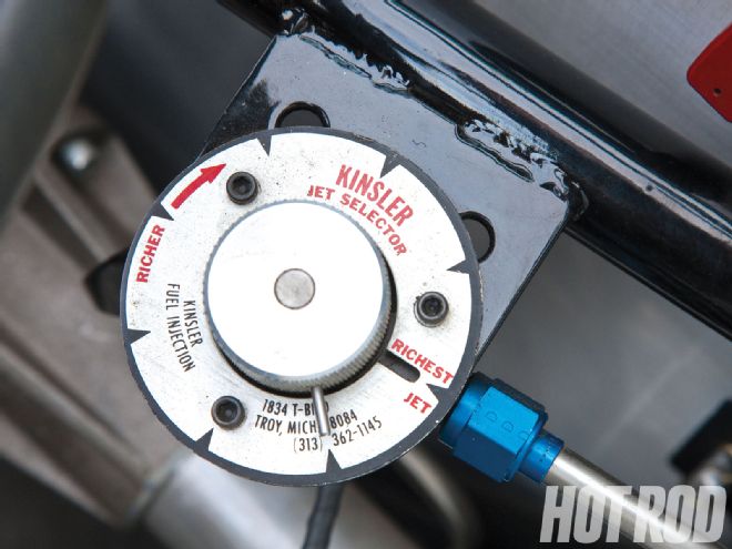 Kinsler's onboard multijet selector allows you to lean or richen the system on the fly, vital if you'll be driving the car for an extended time period. Note: Although a common practice on road racers, fuel in the cockpit isn't legal at the drags.
Nevertheless, some of you will try to run a Hilborn setup on a street car anyway. We're not saying it's impossible-just be prepared for constant tinkering and manual adjustment. If you can get the car to idle and cruise at part-throttle, it will probably be too lean on the top end; conversely, if set up for proper top-end fuel delivery, the idle will be way too rich. Magnetos won't cut it-run a top-of-the-line MSD ignition system. But you'll still change spark plugs often. Only about two guys in every 100 succeed. Those who do invariably run a stick shift and a blower, which seems to put more load on the engine.
If we still haven't talked you out of it, be sure to add a small auxiliary surge tank. It's needed on cars with rear-mounted gas tanks to move the injector's primary fuel supply closer to the engine-driven pump to avoid restrictions in the return lines that cause the engine to run rich. The surge tank also makes it easier to prime the engine for prestart. It should be mounted higher than the injector pump but lower than the barrel valve. This allows gravity feed priming of the pump for easy starting but keeps fuel from flowing by gravity to the nozzles. Remember that the top of the fuel level determines the point of gravity feed. Surge tanks are offered by Ron's Fuel and other sources.
 Don't want to mess with constant adjustment and driveability issues? Hilborn's electronic fuel-injection option provides the excellent part-throttle fuel control absent in constant-flow systems. The common vacuum reference block even resembles the old barrel valve. It's usually cheaper to buy a new EFI-compatible intake from Hilborn like this than convert an existing setup. But of course, for the hard-core retro crowd, it's not right.
Add a shutoff valve between the pump and barrel valve. Closing the shutoff after engine shutdown keeps fuel from running into the cylinders, plus it helps keep the system primed for easy restart. Choose the longest velocity stacks available to enhance midrange torque, along with throttle bodies and nozzles on the small side. For a 350 Chevy, the smallest presently available intake mounts 2 3/16-inch butterflies, which can still support 450 to 500 hp on the street with reasonable driveability. If you can find them, in the '60s Hilborn offered 1 13/16 and 2 1/16 butterfly combos.
There's a direct correlation among nozzle size, pump size, and main jet size. For example, going to a larger pump might call for a larger-orifice jet because of the pump's higher capacity. No. zero rotors in a PG150C pump will usually do the job on the street, with 500ci-plus mills moving up to a No. 1 rotor.
Tuning Fuel Injection
With system in hand, basic tuning starts with first making sure the linkage is properly adjusted. Even a new, factory Hilborn system needs some basic post-installation linkage adjustments, because clearances change as the engine heats up. First check the linkage and butterflies for bind. If necessary, loosen the butterfly screws, pull each throttle shaft front to back several times to center the butterflies, and retighten the screws. With the butterflies closed, use a feeler gauge to obtain the proper clearance between the butterfly blade and the body. Finally, on a V-type engine, adjust the linkage crossbar so both banks open and perform identically. For the finest adjustment, consider measuring exhaust temperatures using a heat gun. Another solution is a Uni-Syn device, available from Hilborn, Kinsler, and other sources.
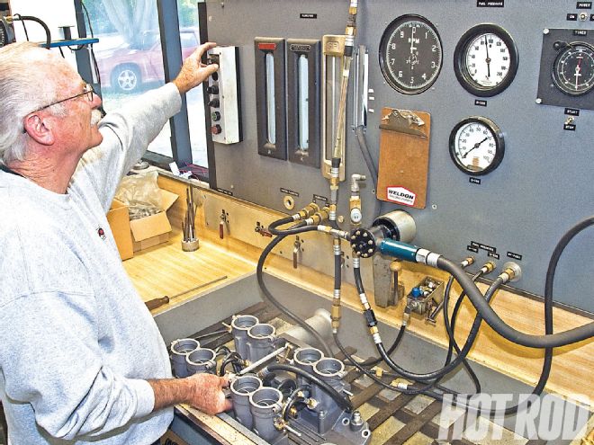 Hilborn Tech Services Director Don Enriquez test-flows and calibrates a complete system. Supposedly identical (same part number) jets or nozzles don't always flow the same amount. Fuel flows through the system at high pressure (more than 100 psi on some high-rpm setups), so minute variations on the inlet and outlet chamfers can greatly alter the actual flow through the orifices.
As for overall system calibration, adjust the barrel valve first to keep response good while also making sure the 60-foot and 330-foot times are strong. One technique is to turn the barrel valve hex link one flat at a time until you get the best throttle response off-idle with no burp or bog.
After setting the idle, tune for full-throttle. By midtrack, the main jet is in control and should be tailored for best times. If running alcohol, you would then adjust the high-speed bypass. Note that a misfueled alky motor can have symptoms that are the opposite from gasoline, so if the car stops pulling or is flat on the top end, it actually has too much fuel. In that case, decrease the shim in the high-speed bypass to lean it out on the top end for best e.t. and mph. Any jet change requires a corresponding change to the high-speed bypass. Every time you richen or lean the motor by one jet size, you must add (for richening) or subtract (for leaning out) one 0.030-inch shim from the high-speed bypass.
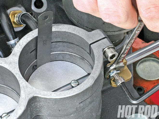 Adjusting the complex throttle linkage is critical. Even on a new factory system, the clearances change as the engine heats up, so the end user must always perform the checks hot as detailed on Hilborn's website. Here, the idle screws on the throttle stops are adjusted to achieve 0.002- to 0.003-inch butterfly opening clearance.
The low-speed bypass is usually adjusted last. Removing shims will lean it down. You may have to adjust the barrel valve hex link again if you've messed with the low-speed bypass.
If this all sounds rather complicated, Hilborn maintains an extensive online tech library and has also posted step-by-step how-to videos on YouTube. The important thing is to have patience and keep a record of your changes. Mechanical injection may be old school and require constant tinkering, but the reward is unsurpassed full-throttle performance that will blow the doors off of just about anything.