Of all of the processes involved in assembling a high-performance engine, properly setting up the valvetrain is perhaps the most critical. Failure to pay attention to the fine points can spell disaster, so it pays to fully understand what to look for as it relates to the engine's requirements. While an engine using mostly OEM parts can typically be bolted together with minimal fuss, as the list of aftermarket and race parts gets longer, it becomes increasingly vital that the system is validated by checking, measuring, and dialing-in the entire system, as required. We stopped in at Andy Mitchell's Outlaw Racing Engines in Upland, California, to look at the principle techniques and tools to do the job on a 509ci big-block Chevy we'll be covering in a future story. Nevertheless, the same ideas apply to all types of engines.
Piston-To-Valve Clearance
It's a fundamental truism that if the valves hit the pistons in an operating engine, the stage is set for an engine failure. Most stock engines leave the factory with generous valve-to-piston clearance, but in a high-performance engine, clearance here can become a scarce commodity. Modifications such as higher compression pistons, more aggressive camshafts, higher rocker ratios, milling, decking, or even the cylinder head design itself can put a crunch on the available clearance. An experienced engine builder considers the depth of the valve clearance notches in the pistons along with all of the above mentioned factors to select parts that will provide the required clearance. Often, when custom pistons are being ordered, the valve notch depth is specified to assure adequate clearance with the engine's parts combination.
When it is all said and done, the only way to know exactly how much piston-to-valve clearance there is in an assembled engine is to directly measure it. There are a couple of different techniques to accomplish this: measuring with a dial indicator at the valve tip, or checking the clearance with the use of clay impressions. Of these two techniques, the clay method is the more foolproof, and it also provides the engine builder with a look at radial clearance to the valve relief, something that the indicator method will not reveal. To check valve-to-piston clearance using the clay method, slugs of modeling clay are strategically placed in the valve pocket of the piston. The cylinder head and valvetrain is assembled, and the crank is rotated through two full revolutions in order to go through both valve events. Next, the cylinder head is removed, and the clearance can be determined by measuring the minimum thickness of the clay impressions.
Spring Load, Installed Height, And Coil Bind
The workhorse of an engine's valvetrain is the valvespring. When functioning properly, the spring's force ensures that the valvetrain is controlled to actuate the valves as intended by the camshaft lobe design. As rpm and the camshaft's specifications become more aggressive, the spring's requirement to maintain valvetrain control becomes more critical. Generally, more spring force is needed to overcome the inertia and negative acceleration of the mechanical valvetrain parts and the valves. Increased spring loads increase the strain on the valvetrain components, as well as the camshaft and lifters, requiring a fine balance between the supplied force and the mechanical limits of the parts.
In selecting valvesprings, the load must be sufficient to provide control for the application, preferably with a margin of extra capacity, while not overwhelming the limits of the mechanical parts. Just where these limits are depends upon the type of camshaft, and just as importantly, the quality of the valvetrain parts. Roller camshafts-such as the one in our 509 big-block here-can tolerate far more spring load than their flat-tappet counterparts, and most manufacturers will base the spring recommendation upon the type of camshaft and the requirements of the lobe design and intended rpm range. Spring loads are given in terms of seat load and open load, which provide the range of spring force over the operating range of the camshaft. Since a spring's force is dependent upon the amount of compression, it is important to pay attention to the actual installed height of the spring.
The installed height is the foundation for correctly setting up the valvesprings. Generally, the manufacturer will provide a specification of spring load at a given installed height, but it is up to the engine builder to confirm the installed height by direct measurement. Once the installed height is determined, the spring can be checked on a spring testing fixture to confirm the spring load at that height, and the noted load can be compared to the requirements of the application. The seat load can be adjusted up by adding shims to reduce the installed height, or the installed height is sometimes increased via retainer and/or valve lock changes or cylinder head machining to reduce the load.
Seat load is only half the picture, however, with open load being the other half. Open load is the amount of force applied by the spring when it is fully compressed at peak lift. Clearly, the first bit of information needed here is just how much lift is being delivered. While the camshaft specifications and rocker ratio can be used to determine the maximum valve lift, the most accurate means is through direct measurement. This is accomplished via mocking up the valvetrain and recording max lift with a dial indicator at the retainer. Subtracting the amount of valve lift from the installed height will provide the open height of the valvespring. The spring can be tested on a valvespring testing fixture at this height to determine the true open load. The seat and open load provided by the spring can then be compared to the requirements of the camshaft. Often, the expertise of the engine builder plays a major role in determining how much seat and open load is appropriate for a given engine combination.
Another critical aspect to be aware of when contemplating a spring combination is the coil bind clearance. The coil bind height simply refers to the height at which the valvespring coils are stacked solid. This specification is listed for most springs in the manufacturer's catalog, or it can be directly measured. Clearly, this relates the spring's physical design to the installed height and the valve lift at which it will be used. As noted, the installed height minus the maximum lift at the valve gives the open height specification. This open spring height has to be above the coil bind height of the spring, plus a margin of safety. Allowing 0.060 inch to coil bind is generally considered a safe margin.
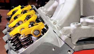
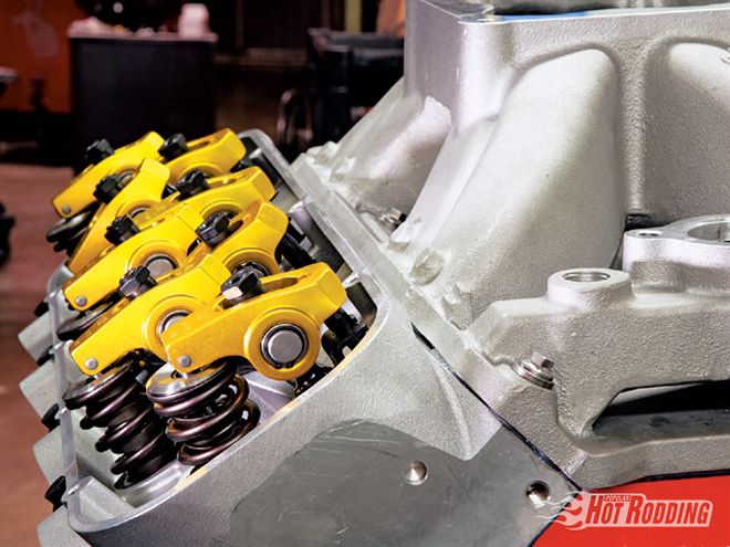
Rockers, Pushrods, And Geometry
Transferring the motion of the camshaft to the valves is the job of the valvetrain. The key components here consist of the lifters, pushrods, and rockers, and can include studs and guideplates, depending upon the engine design. Considering a typical stud-mounted valvetrain as typified by a Chevrolet V-8 engine, there are geometry considerations that need to be kept in mind when setting up the valvetrain. With a stud-mounted rocker, the fulcrum position relative to the valve tip varies in relation to the pushrod length. Most engine combinations assembled with aftermarket rockers, cylinder heads, and/or lifters will typically require pushrods of a custom length. Determining the most appropriate length is part of the engine building process, with the objective being to provide the most advantageous geometry possible.
Ideally, the geometry of the valvetrain will provide for minimal scrub of the rocker at the valve tip, with the contact centered on the valve tip. By varying the pushrod length, the fulcrum height of the rocker is changed, providing the engine builder with a means to adjust the geometry. Typically, the valvetrain is mocked up with a light checking spring in place of the valvespring, and an adjustable pushrod is used to find the most advantaged length. The sweep of the rocker can be verified visually by coloring the valve tip with layout dye or a felt marker, and running the rocker through its motion.
As a general rule, the contact point of the rocker is moved inward to the valley side of the engine as the pushrod length is reduced, while the contact point is moved outward with longer pushrods. The shortest sweep is achieved if the length allows the rocker to achieve a 90-degree operating angle at mid lift. Depending upon the specific parts being used, and the associated rocker length, valve length, and stud position, an "ideal" geometry may not be possible, however, the builder must strive to achieve an acceptable "best compromise" through appropriate pushrod length selection.
In addition to the sweep motion of the rocker at the valve tip, an engine builder must consider the mechanical alignment of the rocker tip to the valve. This entails ensuring that the roller is centered on the valve. In an engine employing guideplates, the lateral alignment of the roller can be adjusted by shifting the guideplate laterally. Again, given variations in specific parts, it may not be possible to exactly center a pair of rockers without modifying the guideplates, however a "best compromise" solution of splitting the difference is usually sufficient unless there is a gross misalignment.