
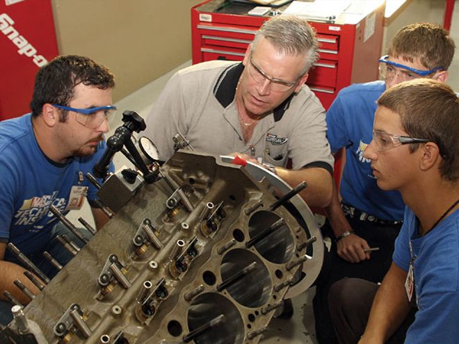
 Craig "The Professor" Hibdon, explains the finer points of degreeing in a camshaft to a class of future racers at the NASCAR Technical Institute in Mooresville, NC.
Checking and adjusting the camshaft timing can be a little bit intimidating to racers or first-time engine builders because it is a bit complex at first. But it is also vitally important because getting it wrong can cost you serious power. Plus, the ability to modify your cam timing can help tailor your engine's power curve to your needs.
Proof of this is the fact that students in the NASCAR Technical Institute's upper-level race engines class begin their course by spending an entire day or more discussing nothing but camshaft timing. Issues such as checking cam timing to make sure it matches up with your camshaft card, advancing or retarding the camshaft to influence power production, and even checking and understanding how such things as overlap, duration, and even total valve lift are taught as a foundation because it affects almost everything else.
 Precisely finding piston top dead center is the first task in degreeing a cam. Fortunately, this can be done with the degree wheel and a pointer (which you will be using for the other tasks) as well as a piston stop.
We understand that long how-to articles about degreeing in a camshaft can make a reader's eyes glaze over, but when we heard instructor Craig Hibdon's methods for teaching camshaft timing and how well his students responded to it, we asked if we could base an article on his class. The NASCAR Tech Institute's method for degreeing a cam isn't unique; in fact, most engine builders follow some variation of this method. But the methods Hidbon uses to present these sometimes difficult concepts are about as simple and easy to understand as we've ever heard. So, turn to page one in your textbooks class, we're about to have some fun.
Finding piston TDCTiming your camshaft involves measuring total lobe lift, the lobe centerlines for both the intake and exhaust lobes, camshaft duration at 0.050-inch lift, and lobe separation. But before we can do any of that, we first have to find the crankshaft location when the piston in the number-one cylinder is at top dead center (TDC).
After you have installed your crankshaft and camshaft and connected the two with your timing set, take a moment to make sure you have your cam installed "straight up," which means the tick marks on the timing gears point toward each other. At this point, the camshaft should be installed as your cam manufacturer intended. But it should always be checked because any number of variables can throw off cam timing. These factors include, but are not limited to, an improperly marked timing chain, errors when machining the block, assembly errors, or even an improperly ground camshaft.
 You can purchase kits with dial indicators made to fit into the lifter bore to measure lobe lift, but all you really need is a dial indicator with a feeler extension and a moveable magnetic stand such as you see here. For best results, you want no lubricant on the lobes when making your measurements.
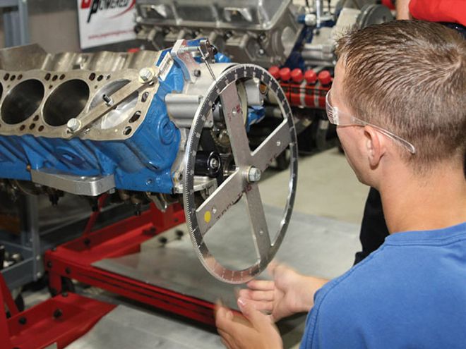
To find piston TDC, you will need a degree wheel attached to your crankshaft, a degree-wheel pointer, and a piston stop. Install the degree wheel on the nose of the crankshaft and position your pointer-often just a piece of wire-over the degree wheel, as close as possible without touching it. Your piston stop can thread into the spark plug holes or simply be a strap that pulls over the deck of the block. It doesn't matter as long as it keeps the piston from reaching TDC.
Slowly spin the crank clockwise until the top of the piston contacts the piston stop, and check the position of the pointer on the degree wheel. Count up from the zero mark on the wheel and make note of it. Now, slowly spin the crank counterclockwise until the piston makes contact with the piston stop again. And once again, make note of the degrees on the degree wheel in the direction closest from the zero mark. In other words, both of your readings should be less than 180 degrees. Now, find the average of those two numbers. For example, if your readings were 36.75 in the clockwise direction and 35.25 when turning the crankshaft counterclockwise, the average is 36 degrees.
Remove the piston stop and spin the crankshaft until the pointer is over the 36-degree mark, which is between your two readings. Your piston is now at TDC. Readjust your degree wheel-without allowing the crankshaft to move-so that the zero mark on the wheel is underneath the pointer. Now we are set to get to work.
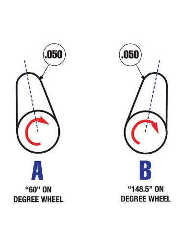 To determine lobe centerline, measure at 0.050 on either side of maximum lobe lift and take your readings from the degree wheel. The average of those numbers is your centerline. For example, if your readings are 60 degrees when the lifter is 0.050 before maxium lobe lift (A) and 148.5 degrees when the lifter has dropped 0.050-inch after maximum lift (B), then your centerline is at 104.25 degrees.
Measuring lobe lift is extremely simple. All you need is a valid indicator with an extension so you can reach the cam lobe through the lifter bore. The indicator should be in the same line that the lifter would follow in order for the readings to be accurate.
Spin the crankshaft until the dial indicator is on the cam lobe's base circle. That is the area on the back side of the lobe that provides zero lift. When you know the dial indicator is on the base circle, zero out your gauge. Now, spin the crank and keep an eye on the indicator. As the lobe moves underneath the end of the dial indicator, the needle will start moving. Watch until the needle stops and begins to move in the opposite direction. This is maximum lobe lift.
It is important to note that lobe lift is not the same thing as valve lift. If you are checking against your cam card, make sure you are looking at lobe lift numbers. To determine total valve lift, multiply your maximum lobe lift findings by your rocker ratio. For example, if total lobe lift is 0.420-inch and you are using 1.6:1 ratio rocker arms, your total valve lift should be 0.672-inch.
The lobe centerline is defined as where max valve lift occurs and is measured in terms of crankshaft degrees from piston TDC. Lobe centerline is often-but not always-the halfway point of that lobe's duration. When this happens, it is called an "asymmetrical lobe" and is usually reserved for ultra high-end race cams.
Begin with the dial indicator in place on the intake lobe for the number-one cylinder and rotate the crankshaft clockwise until you reach the valve's maximum lift. Zero out your dial indicator. Now rotate the crank counterclockwise until you have dropped at least 0.100 in valve lift. Spinning the crank clockwise again, turn the engine until the dial reads 0.050. The 0.050 is our target number, but we went beyond it and then came back because you always want to take your readings with the engine turning in the same direction it will be when running. Slack in the timing chain can throw your readings off if you take any measurements when spinning the engine backwards. If you have all eight pistons installed, the rings can make turning the engine over and hitting your marks difficult. If you accidentally go too far, back up and try again. Just do not take any readings directly after turning the crank counterclockwise.
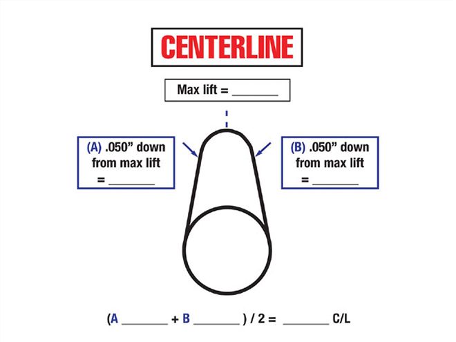 The NASCAR Technical Institute's worksheet for determining lobe centerline. Courtesy of NTI
Once you have the indicator on 0.050, take a reading from the degree wheel. Most degree wheels allow you to measure in degrees from TDC (the zero mark) in both directions. Count the degrees from TDC to your pointer along the shortest path. In other words, your reading should be less than 180 degrees. Once you have that measurement taken, rotate the engine clockwise past maximum valve lift until it has dropped 0.050 on the other side. Take your measurement from the degree wheel once again. And again, take the shortest path as you count up from the TDC mark to the pointer (it should be less than 180 degrees).
Your centerline is the average of those two numbers. For example, if your readings were 60 and 145.5 degrees, then your centerline would be 102.75. This means that the intake valve reaches max lift 102.75 degrees after the piston has reached TDC. Repeat the process again for the exhaust valve.
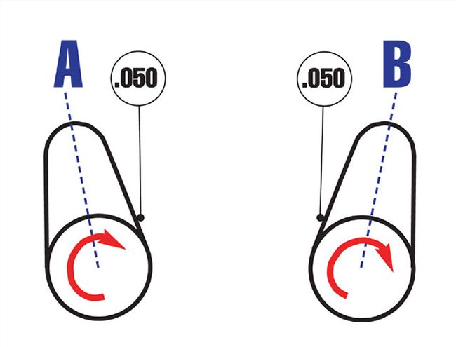 The process for measuring duration is similar to finding lobe centerline, except you measure when the lifter is raised 0.050 off the cam's base circle, or zero lift, (A) and again when the lifter is 0.050 away from being on the base circle again (B).
Once you are able to determine your lobe centerline, it is possible to influence your engine's power band by advancing or retarding the camshaft's position relative to the block. There are several different ways to change your cam timing, but all vary the relationship between the cam gear and the crank gear in some way.
Advancing the cam timing moves the valve opening and closing events earlier in the cycle. Since the relationship between the intake and exhaust lobes cannot be changed, advancing or retarding a cam affects both the intake and exhaust valve equally. Also, the most important thing advancing or retarding a camshaft affects for engine power is when it closes the intake valve. For example, if the camshaft is advanced, the intake valve closes sooner. This typically increases cranking compression on a high-duration race cam. The result is more torque and power in the lower rpm ranges. But as the rpms increase, the velocity of the air/fuel charge in the intake ports also increases dramatically and the early intake valve closing hurts power.
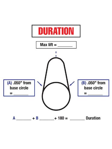 The NASCAR Technical Institute's worksheet for determining duration. Courtesy of NTI
On the other hand, if the camshaft is retarded, the intake valve will close later (usually sometime during the compression stroke). As you might expect, this drops cranking compression and hurts low-rpm power. But as rpm increases and cylinder filling is aided by the extreme velocity of the air/fuel charge in the ports, a retarded camshaft will help power. Usually, the change-either advancing or retarding-should be less than eight degrees. If you need to go more than that you should consider using a different cam.
Duration is the amount of time the valve (either the intake or exhaust) is open. Like centerline, it is measured in terms of degrees of crankshaft rotation. This number is fixed once the crankshaft is ground and will not change if it is advanced or retarded.
There are two types of durations, typically called "advertised" and "at 0.050." The difference is a matter of measurement, specifically when you consider a valve to be open. Advertised duration is the number that the manufacturers supply. But you cannot compare advertised duration numbers because almost all manufacturers use different valve lift numbers to begin measuring duration. One manufacturer may begin measuring duration at 0.003 of valve lift while another may use 0.006. Also, because the lifter is still moving relatively slowly at such low lift numbers, it is quite hard to accurately measure.
The tactic most engine builders take is to mainly concern themselves with duration at 0.050. This means the number of crankshaft degrees the cam holds the valve open from the point that it raises 0.050-inch off the seat until it is lowered to within 0.050 from the seat. Most cam cards will provide duration numbers at 0.050, and it is easy to measure at this amount of lift.
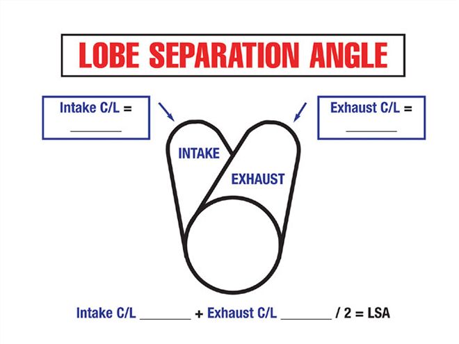 The NASCAR Technical Institute's worksheet for determining lobe separation angle. Courtesy of NTI
Begin as you did before with a dial indicator on the lobe of the cam. This time, however, position the cam so the dial indicator is sitting on the base circle (zero lift) and zero out the dial. Rotate the engine in the normal direction of rotation until you have 0.050 lift and look at your degree wheel. Count your degrees from either TDC or BDC (whichever is closer) and make a note of it. This is your opening number.
Next, continue rotating the engine through camshaft max lift and stop when the lifter is 0.050-inch from the base circle. Again, count the degrees from either TDC or BDC to the pointer and note it. This is your closing number. Both the opening and closing numbers should never be more than 90 degrees. To find duration, add your opening number, plus your closing number, plus 180 degrees. For example, if your opening number is 38.25 and your closing number is 67, your duration for that lobe would be 285.25.
When checking duration, you should check both for the intake and exhaust. More duration in a camshaft, both for the intake and the exhaust lobes, is usually useful for racing. Just like retarding a cam, a longer duration will delay the valve closing, which can lower cranking compression but will allow for greater cylinder filling at high rpm levels.
The lobe separation angle is a measure of the relationship between the intake and exhaust lobes for the same cylinder and the only measurement discussed in this article that is measured in camshaft degrees of rotation. Lobe separation angle (LSA) is found by adding the intake and exhaust centerlines and then dividing by two. Typically, a camshaft with a wider LSA (higher numerically) will have less overlap than a camshaft with a narrower angle. But don't be fooled into thinking that LSA always goes hand-in-hand with overlap. A race cam with a 112 LSA may have more overlap than a street cam with the same LSA. That is because the race cam will almost certainly have lobes with more duration, which also creates more overlap.