 The Ford 2300 engine has proven itself reliable for four-cylinder racing classes and delivers strong performance at 7,500 rpm.
This is part two of the buildup for the engine used in a Mustang Ministock project undertaken by Steve Smith Autosports. The first portion of the buildup can be found in March '04 Circle Track. The entire buildup can be seen in a video presentation available from Steve Smith Autosports. The book, Building the Mustang Ministock, is also available. Contact Steve Smith Autosports Publications at 714/639-7681 or www.stevesmithautosports.com for more information.
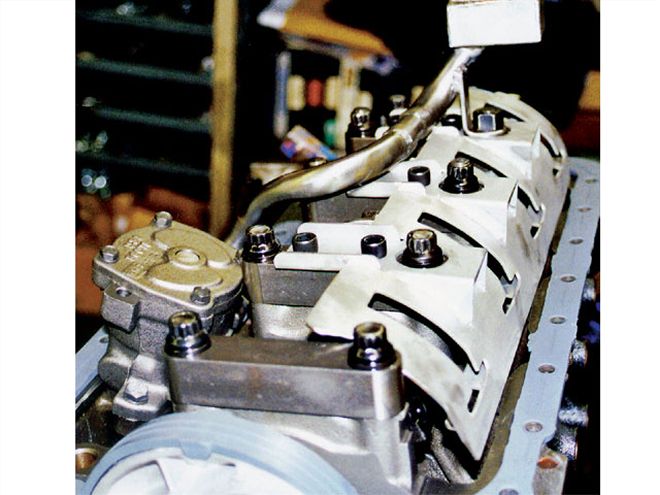
The process of building this engine is well under way, but we're still far from finished. The engine uses solid lifters (adjusters). Although most racers refer to them as solid lifters, they are actually solid adjustable posts. One end of the rocker arm pivots on this post. The height of the post is adjustable to provide the proper amount of valve lash. In this system, lash is set between the cam follower and the camshaft.
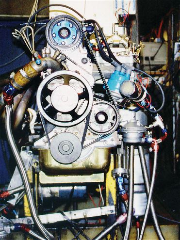
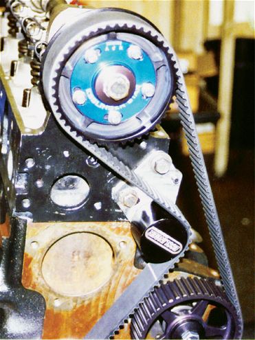 Don't skimp on this part. The Esslinger heavy-duty timing belt assures more reliability with better quality material. The belt tensioner is machined from billet aluminum and anodized.
Valve lash is a clearance in the drivetrain designed to compensate for thermal expansion of valvetrain components as the engine heats up. Tightening or loosening the valve lash (by the camshaft manufacturer's recommendation) will result in timing changes when the cam lobes make contact with the cam followers.
The stock 2300 engine uses hydraulic valve lash adjusters. Some tracks require the stock part while others will allow the conversion to solid adjusters.
There are advantages to solid adjusters. Lash adjustment can be more positive. In addition, higher rpm can be achieved, and this opens the door for a much greater selection of cam grinds. If you want to convert hydraulic adjusters to solid, Esslinger Engineering offers a kit. When this kit is installed, hydraulic lifter bore bosses must be milled 0.3 inch lower. If you are stuck with hydraulic, Esslinger has anti-pump-up hydraulic adjusters that allow the engine to reach a higher rpm.
The cam is driven by a cogged belt from the crankshaft. The belt drives the auxiliary shaft, which turns the oil pump, fuel pump, and distributor. Preload on an idler pulley maintains tension on the belt. It sounds simple, but these parts must be correct and aligned in order to provide engine life and reliability for racing conditions.
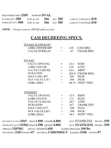 For this project, an Esslinger cam No. 2269 was chosen. This is the spec sheet for the part.
The timing belt and belt tensioner play critical roles. If the timing belt breaks, it's valvetrain disaster. On this engine, an Esslinger heavy-duty timing belt was used with materials much tougher than stock. The Esslinger belt tensioner is machined from billet aluminum and anodized. This roller prevents failure of the stock two-piece stamped unit.
The belt tensioner must be respected and not used as a wedge with a large screwdriver when mounting the timing belt. During racing season, check the belt tensioner for tire rubber buildup and clean it often.
The Ford 2.3 engine has head locator sleeves that should be placed around the front and rear head bolts. The cam belt will not run properly if these sleeves are not used. If the head and block have been milled, the sleeves will need to be shortened by a like amount.
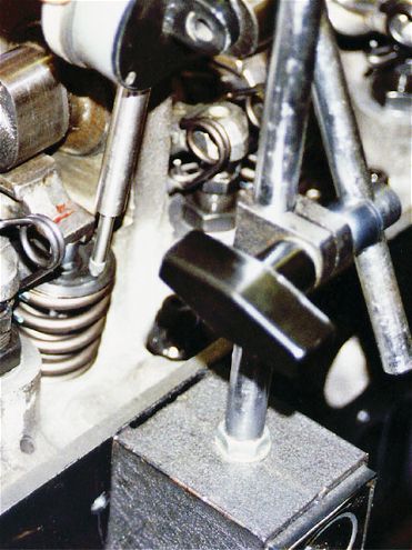
 This tool was used to press in cam bearings. There's a 1/16-inch pipe plug in the top oil hole.
The major problems with stock rocker arms are camshaft lobe wear and arm breakage. Esslinger's heavy-duty cam followers have a softer contact pad for the cam lobes to greatly reduce wear. The wear pad is a separate piece, oven-brazed to the arm. It holds oil, which prevents lobe wear and scuffing.
The use of roller rocker arms with a cast camshaft can cause a significant change in valvetrain geometry. Use roller rockers on billet camshafts only.
Camshafts Most Ministock rules allow the use of an aftermarket solid adjuster camshaft, but there are exceptions. Check your rules. An excellent choice for oval track applications is the Esslinger model 2269, which delivers good torque and power between 4,000 and 8,000 rpm. Be sure to get the entire cam kit, which includes heavy-duty valvesprings and retainers.
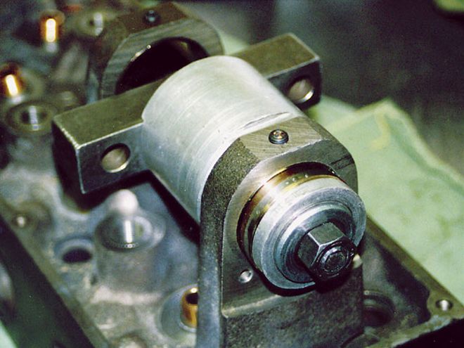
 The E Bar method has been developed by Esslinger Engineering to assist in degreeing the cam.
Replacement cam bearings for the 2300 do not provide oil to the cam bearing journals for which the stock system was designed. The original design called for pressurized oil to be supplied at the top and the bottom of the cam tower into the bearings. With replacement bearings, oil feeds from the bottom around a groove in the back of the bearing, then feeds through a hole in the bearing. This bearing design means plugging the top oil feed hole at the top of each cam tower. Drill and tap the holes for 1/16-inch pipe thread and use a 1/16-inch pipe thread plug.
When installing, always use a new cast camshaft and new cast rocker arms together. They must break in together and become hardened together. Use caution when installing the cam to avoid damaging the bearing surfaces. Once the cam is in place, the pulley can be installed. Esslinger makes an adjustable pulley that allows timing the cam with pinpoint accuracy.
Because the center cam pulley bolt doubles as an oil gallery plug, install it with two rounds of Teflon tape, three rounds back from the end. This will adequately seal the threads to prevent a leak. Liquid Teflon may be used instead of tape.
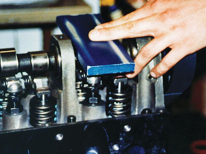
 When the E Bar is equal in distance to the rocker cover seat on both sides and the crank is at TDC, the cam will be degreed as close as it can be. See the story for a complete explanation of the E Bar method.
During camshaft installation, coat all moving parts with assembly lube. Esslinger Engineering recommends black Molykote on the cam lobes and Alisyn Pro 21 on the bearings. Before your engine is started for the first time, add a bottle of Crane Cams' Break-In Concentrate to the engine oil. The anti-wear additives provide protection against cam and follower scuffing and wear during break-in.
To degree the cam, Esslinger has developed the E Bar Method:
1. Put the crankshaft on top dead center (TDC).
2. Lay a 2x9-inch piece of 1/4-inch aluminum plate across the camshaft, teetering it across the number one exhaust and intake lobes as they form a shallow "V."
3. Have a belt hooked up in approximately the normal position.
4. Loosen the three bolts and the center bolt on the face of the cam pulley.
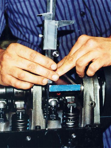
 Measuring total valve lift (TVL).
5. Grasp the camshaft in a non-lobe area with large pliers. Rotate the cam until the aluminum plate is parallel with the ground. Measure from the aluminum plate to the surface where the rocker cover sits. When it is equal on both sides and the crank is on TDC, the cam will be degreed as close as it can be.
6. Tighten the three bolts and the center bolt on the cam pulley.
7. Using a sharp file, re-index the outer pulley at zero. Each mark equals two crankshaft degrees.
8. Putting the index line on the outer pulley between the marks on the inset allows you to advance or retard the cam in one-degree increments.
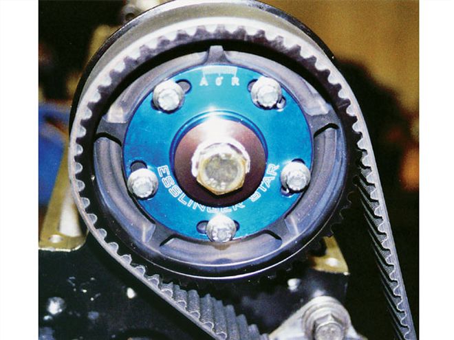 On this project, we used an adjustable camshaft timing pulley. This will assist in quick timing changes at the track.
If you want to advance or retard the cam at the track, loosen the three bolts and the center bolt on the camshaft pulley, and then put a wrench on the crankshaft bolt and move the crank.
All clearances need to be correct before final assembly. The clearance between the valve-guide and retainer should be a minimum of 0.2 inch with the valve open. Minimum clearance between the valve seal and retainer should be 0.05 inch with the valve open. The clearance between the piston and valve should be a minimum of 0.09 inch. If an adjustable cam pulley is used, check this clearance with the cam set 6 degrees advanced and 6 degrees retarded.
To check valve lift, follow these steps:
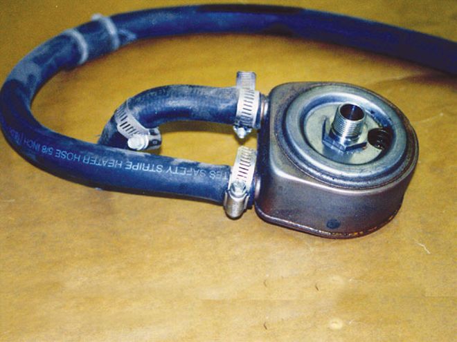 A water-cooled heat exchanger, like the part found on the turbocharged '83-'89 Thunderbirds, works well in this application.
1. Install the solid lifters.
2. Install the valves, valvesprings, retainers, and keepers properly.
3. Install two rocker arms on the number one cylinders.
4. Adjust the solid lifter so that the follower is at zero lash. Always measure the lash between the lifter and the base circle of the cam.
5. Place a dial indicator on the retainer so that it is at the same angle as the valve stem. Reset it to zero.
6. Rotate the cam to find the maximum lift shown on the dial indicator. This will be total valve lift (TVL).
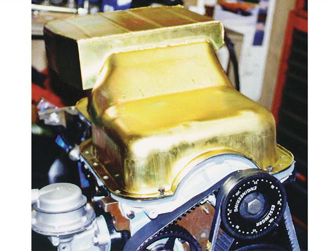 A properly designed oil pan holds a key to performance. The Canton Racing Products PN 11-910 filled the bill for our car.
If the TVL is higher than the cam spec sheet, the valve needs to be lengthened. If the TVL is lower than the cam spec sheet, the valve will need to be shortened. The rocker arm ratio will change through cam rotation, but, in general, shortening the valve by 0.05 inch increases lift approximately 0.025 inch.
Upon completion of cylinder one, move to the next cylinder. When TVL has been measured on all valves, reset the valve lash to 0.01 inch. The procedure will bechanged somewhat if you're using hydraulic lifters.
When the head is milled, the cam drops closer to the crank, causing the belt to loosen and timing to retard. Esslinger manufactures an adjustable cam timing pulley, which will take up the slack in the belt and provide a quick method of setting timing at the track. Do not adjust the pulley more than six degrees either way. If you need more adjustment, you probably need another cam profile.
 Three trap door baffles and three directional runners make sure the oil is always surrounding the oil pump pickup. There's no oil starvation during cornering, acceleration, and deceleration.
Use the two stock cam belt guide plates. One is located behind the cam pulley and the other is on the crank in front of the cam belt drive gear. If the cam belt runs off the cam pulley, you have a bent belt tensioner, or the crank gear may have been installed backwards.
The intermediate shaft operates the fuel pump, oil pump, and distributor drive. A stock intermediate shaft is made of cast iron with a cast gear and cast distributor gear. These can break under racing use, so Esslinger developed a replacement shaft, which is machined from billet chromoly steel and uses a steel shaft gear and bronze distributor gear. Higher oil pressure levels can be used without reliability issues.
Coat the shaft liberally with assembly lube before installing. The gear and fuel pump eccentric cannot touch the bearing surfaces during insertion. Shaft bearing oil holes must be aligned with the oil holes in the block.
Esslinger's intermediate shaft bearings should be used with the steel replacement shaft because the bearings have three extra sideways grooves to provide additional oiling of the distributor gear.
A windage/anti-slosh baffle controls the oil off the crankshaft.
The stock oil pump on a 2.3 engine will work sufficiently with modifications. A suggested replacement is the Melling High Volume M-86 CHV pump. The 2.3 engine requires 75 psi oil pressure at 7,500 rpm. Install a 1/8-inch spacer behind the stock spring in the pump.
The ideal oil pressure for the 2.3 engine is 10 psi for every 1,000 rpm. A major problem with the 2.3 engine is that the center main bearing will knock out if oil pressure is insufficient. Excessive oil pressure can also cause problems such as wasted power, higher oil temperature, and stress on oil pump drive components.
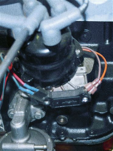 A hybrid was created. A stock 2.3 electronic ignition was modified with a GM HEI module adapted to the magnetic pickup of the Ford distributor.
The ideal oil temperature for a 2.3 engine is 180 to 200 degrees. While 220 is acceptable, oil will start to degrade and lack lubrication strength at temperatures much above that. Overheating will crack a block quickly. Oil that is too cool (below 150 degrees) will foam quickly and not lubricate well. To combat engine oil temperature problems, let the engine idle before running at high rpm.
A heat exchanger will help oil cooling. An ideal part can be found in the '83-'89 turbocharged Thunderbird and Mustang SVO. It is a water-cooled oil cooler. The heat exchanger can be placed well back in the engine compartment to protect it.
The oil pump/distributor drive system is the weak link in the 2.3 engine. The demands of racing are hard on the stock drive. Proper warm-up of the engine oil can help. Let the engine idle without revving. Cold oil does not flow well, and revving the engine while the oil is cool will cause pressure spikes in excess of 120 psi, which can cause instant failure of the intermediate shaft, distributor gear, or drive pin.
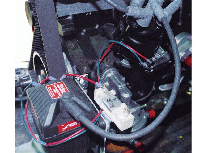 Mallory's Promaster coil was used for this ignition system.
Esslinger Engineering recommends fabricating a replacement distributor roll pin. Start with a 3/16x2-inch-long Grade 8 Allen bolt. Grind down the head so that it looks like a nail. Cut the threaded portion of the bolt so that it is just longer than the diameter of the distributor gear. Drill the distributor gear and distributor shaft so that the pin will fit with a little interference. Center-punch the end of the pin so that it will not fall out.
A properly designed oil pan plays a key role in keeping a high-revving racing engine alive. Pans need to be designed with internal baffling, a windage tray, trap doors, and a crankshaft scraper, along with utilizing an oversized oil pump pickup. We used a Canton Racing Products pan (PN 11-910) that holds five quarts of oil. It has three trap door baffles, three directional runners, a bolt-in windage/anti-slosh baffle, and a magnetic drain plug. We used Canton's 0.75-inch OD tubing pickup (PN 11-911).
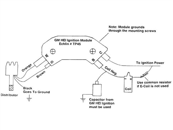 Follow the wiring diagram to set up the system. Make sure there is proper ground and all connections are solid.
Controlling the oil in the pan and keeping it off the crank and other rotating parts can gain 5 to 10 hp. If the oil supply should slosh away from the pickup, a gulp of air could ruin the bearings. The pickup should be 1/8 to 3/16 inch from the bottom of the oil pan floor. The crankshaft-to-oil-pan scraper should have a 1/16- to 1/8-inch clearance.
The stock Pinto 2.3 electronic ignition can be inexpensively modified for racing. A General Motors HEI module can be adapted to the magnetic pickup Ford distributor. The ignition module mounts at the distributor base where the vacuum advance goes. When installing, use the grease that comes with it to dissipate the heat. When using this system, install the Ford E Coil. If you use a standard coil, use the stock capacitor mounted to the battery side of the module. This is not required with the E Coil. You cannot control the advance in the late model 2.3 Mustang distributor, so it is not an acceptable option.
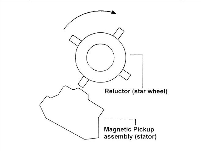 The ignition signal is generated as the reluctor passes and leaves the pickup. Align the advance plate so that the trailing edge of the reluctor lines up with the magnetic pickup.
To mount the GM HEI module, remove the vacuum advance. File the external surface flat and drill and tap for machine screws. Align the advance plate so that the trailing edge of the reluctor lines up with the magnetic pickup, and the rotor, as installed, points toward a terminal on the distributor cap. The ignition signal is generated as the reluctor passes and leaves the pickup. Spot-weld the advance plate in this position and the distributor should be phased properly. You can check the arc marks to see where the rotor is actually firing. The capacitor from the GM HEI ignition must be used. The capacitor is available with a modular plug or bullet-type connector.
The ignition module can be mounted away from the distributor (up to four feet). Mount the ignition module to a finned aluminum heat sink, and run the orange and brown distributor leads through metallic shielding to prevent radio static interference. The module housing must be grounded to the engine. Always use a special grease under the module so it radiates heat properly.
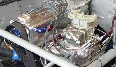
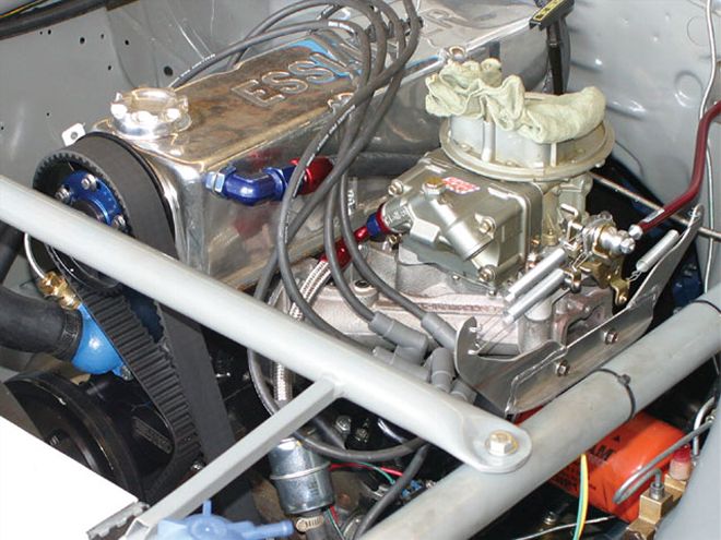
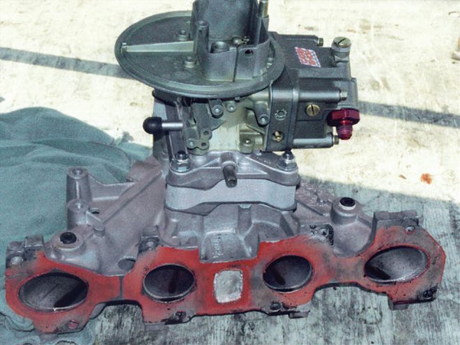 A Holley 350-cfm carburetor was modified by Carb Shop. The intake manifold is a Holley part designed for the round port head. An Esslinger 1-inch spacer is also used.
If you have problems getting spark, here's how to diagnose the problem:
1. Crank the engine to see if the distributor turns. Check for a spark from the coil secondary wire to the ground. If you have a spark from the coil, the problem is with rotor phasing, or the spark is going to ground under the cap or rotor
2. Check the distributor across the orange/brown leads using a digital volt/ohm meter set on two volts AC (yes, AC). At cranking speed, it should make at least 0.6 to 0.8 volts AC, but more likely 1.2 volts AC.
3. Check the coil. Both coil leads have juice with the ignition switch on. The module momentarily grounds the negative side of the coil, causing it to charge. The coil fires when the module releases the ground, just like good old-fashioned points. Use a 12-volt test lamp and momentarily ground the negative coil terminal through the lamp when the ignition switch is on. You should observe a small spark from the coil secondary wire to ground each time you disconnect or release the circuit.
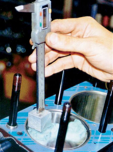 Clearance checks are critical. Modeling clay is used to determine piston-to-valve clearance.
4. If the distributor and coil are fine, the problem could be wiring, a bad ignition module, bad capacitor, or something not grounded.
The advance curve for the 2300 racing engine is the same whether a dual point or electronic ignition system is used. Recommended total spark timing advance is 36-38 degrees at 3,000 rpm. The total spark advance is a combination of the advance mechanism in the distributor and the advance set with the timing light at the crankshaft. The distributor rotation is one-half the crankshaft rotation, so to find total advance, double the full advance of the distributor, and subtract this figure from 38 degrees.
The two most common carburetors used in this application are the Holley 350-cfm and the Holley 500-cfm, as determined by track rules. If it is allowed, the 500-cfm should be used for its airflow advantages. This car is using a 350-cfm model, modified by Carb Shop.
If you're using a 350-cfm model, start with the No. 68 main jets, a No. 35 power valve, and install Holley's Off-Road Kit. If you're using a 500-cfm model, start with the No. 70 main jets, a No. 35 power valve, and install Holley's Off-Road Kit. The Off-Road Kit includes a spring-loaded needle and seat and a vent whistle, which is an air vent that helps control fuel sloshing.
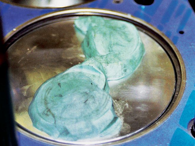 The valves will leave an impression in the modeling clay. Measure the height of the impression to obtain the valve-to-piston clearance.
Pay attention to the fuel mixture for the two center intake ports. You may have to stagger carburetor jets to equalize mixture. A 1-inch spacer between the carburetor and intake manifold can be helpful.
Make sure to match your intake manifold to the heads being used.
It takes time to put an engine together, so don't rush. Check and double check everything at every step of the process. Keep all parts close at hand, clean, and ready to go. Parts such as rods, pistons, etc., should be kept covered with airtight plastic once they are prepared.
Before final assembly, double check all clearances including bearings, deck height, valve-to-piston, valve relief, and rods.
 Esslinger Engineering's dyno was used for break-in, testing, and tuning. The maximum horsepower figures checked in at 174.6 at 7,000 rpm.
An inherent design flaw of the 2.3 engine and other inline four-cylinders is that they vibrate in high frequency, which loosens fasteners, even if properly torqued. Use Loctite or safety wire on all critical bolts and nuts. When torquing the head, intake manifold, and exhaust manifold bolts, do so in two progressive steps, following the proper bolt sequence. Use a thin coat of red Loctite around the cam and main seals. Silicone sealer (red, blue, or clear) makes an excellent seal and can be used in place of some gaskets. Silicone sealers should not be used around carburetors and fuel systems.
After final assembly, use a leakdown tester. Using 3 to 5 psi pressurized into the rocker cover can show if there are leaks in the rocker cover gasket, pan gasket, main seal, or cracks in the oil pan. Before the engine is started for the first time, it must be pre-oiled by manually rotating the oil pump. Use the shaft from an old distributor and connect a hand drill to it. With a newly assembled engine, or when a new cam and followers have been installed, use a 20W50 racing oil. Add a bottle of Crane Cams Break-In Concentrate. Run the engine nonstop for a minimum of 30 minutes at 2,500-3,000 rpm. Vary the throttle occasionally to change the oil pressure and oiling pattern, but do not rev.
 Complete information about the buildup of this car can be found in the book Building the Mustang Ministock. It is available from Steve Smith Autosports, 714/639-7681, www.stevesmith autosports.com.
* Cylinder head bolts, 85
* Cylinder head studs, 90
* Main bearing cap bolts, 85
* Main bearing cap studs, 90
* Connecting rod bolts (per mfg.)
* Header bolts, 25
* Intake manifold bolts, 30
* Cam pulley bolts, 50
* Piston to bore, 0.003 to 0.005
* Piston ring end gap, 0.017
* Main bearings, 0.002 to 0.0025
* Connecting rod bearings, 0.0025 to 0.003
* Crankshaft endplay, 0.004 to 0.008 (big main block)
* Connecting rod side clearance (stock), 0.007 to 0.012
* Connecting rod side clearance (forged), 0.010 to 0.015
* Wristpin, 0.0008 to 0.001