It is incomplete to even talk about degreeing a camshaft without discussing piston-to-valve clearance. It's like learning how to drive but never being taught how to use the brakes. Learning how to make the car go is nice, but it's critical to understand how to make it stop! It's the same way here: Having the camshaft off by a degree or two never blew up an engine, but banging the valves into the piston top sure has.
The only way an engine will blow up after being degreed in wrong is if there is a lack of piston-to-valve clearance-the further you advance a camshaft the less intake valve-to-piston clearance you will have; conversely, the further you retard a camshaft the less exhaust valve-to-piston clearance you will have. I think you can see the importance of the relationship between degreeing a cam and the piston-to-valve clearance.
I know a lot of guys who are willing to trust the cam card and will plug in exactly the rocker-arm ratios the cam card tells them to. But as soon as you start playing with different combinations-which is what you are going to have to do if you hope to find a horsepower advantage-you are on your own. Don't ever assume you have enough piston-to-valve clearance unless you have plenty of money and are willing to learn the hard way. Hopefully, if you are that kind of guy, you are buying your pistons and valves from me. This also applies to anyone who thinks the process of checking piston-to-valve clearances is too time-consuming. Rebuilding your engine because you have needlessly bent all the valves is what is really time-consuming.
Mock-up Engine
So what is involved in checking piston-to-valve clearances with the degree wheel? Glad you asked. It's really not all that difficult. One note: Although checking piston-to-valve clearances isn't tough, there are several steps. Probably the easiest way to get the gist of how we do this is to take this copy of Circle Track to your shop and try each step on an engine as you read along.
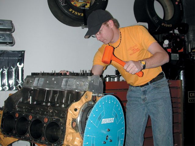
Once you have all your parts ready to assemble your engine, it is time to mock-up your short block. Set your crank, cam, timing chain (or belt), and your No. 1 piston and rod assembly in the engine. Don't be afraid to put the top ring on the piston for stability, and attach the cap on the end of the rod with fasteners for safety. Although this is a mock up, we still need to lubricate the parts as if it is the final assembly. At this point I like to put my degree wheel on and use a dead stop to find my TDC (top dead center) mark.
With your degree wheel in place, go ahead and set your cylinder head on the engine and fasten it securely with a couple of fasteners. Your cylinder head should have the intake and exhaust valve in place for the cylinder we are checking. I also like to install valve seals to ensure the valves will not fall out. At this point using the head gasket is optional; but if you decide not to use one remember that you must add the compressed thickness of the head gasket to your final piston-to-valve clearance figure to be accurate.
Now that your cylinder head is securely fastened to the engine block, it is time to set up your dial indicator to indicate valve travel.
We will be checking our piston-to-valve clearance for the intake valve at TDC and 10 degrees ATDC (after top dead center), and the exhaust valve at TDC and 10 degrees BTDC (before top dead center). The locations are where the piston and valves will be the closest through the cycle.
With your dial indicator on the exhaust valve, turn the degree wheel clockwise to 10 BTDC, making sure the valve is securely closed and your dial indicator is at zero. Next, slowly move the exhaust valve down toward the piston while you are watching the reading on your dial indicator. Once the valve is firmly against the piston and will not move down any farther, write the reading from the dial indicator on a piece of paper. This is your valve drop for the exhaust valve.
Here is a technical term to remember: "Valve drop" is the action taken while properly building an engine, and "dropping a valve" is the action taken before taking an engine apart.
Now, pull the exhaust valve back to its shut position and check that the dial indicator returns to zero. If it doesn't, then repeat these steps to ensure accuracy. Once you are comfortable with the reading from your dial indicator and you have it written down, slowly rotate the crank clockwise until it reaches the TDC mark. Go ahead and check the valve drop at TDC and record that figure. Be sure to neatly label your measurements so you will not get them mixed up.
After you return the exhaust valve back to its closed position, and with your degree wheel marking piston TDC, go ahead and put your dial indicator on the intake valve. Make sure the intake valve is firmly shut then zero the dial indicator. Proceed with the valve drop just like you did with the exhaust valve at TDC, and then at 10 ATDC. Again, it is very easy to get these figures mixed up, so label them clearly.
Keeping your figures organized is important because it prevents your machinist from needlessly cutting the valve pockets in the pistons too deep. By creating too much clearance, all you have done is reduce compression.
Valvetrain Added
Next, you can remove the dial indicator. You should have four figures written down. Install the lifter in the lifter bores of the cylinder you are checking, along with the rest of the valvetrain to connect the lifters to the valves. You can install "checking springs" instead of the real thing to make rotating the crank a little easier. It doesn't matter as long as the spring is strong enough to allow you to set the valve at zero lash. Once you have everything in place, set the valve lash to zero and reset the dial indicator on the intake valve. Make sure the indicator is set on the edge of the spring retainer so that when the valve is fully open the end of the rocker arm does not hit the dial indicator.
When installing your rocker arms it may be necessary to rotate the engine until both valves are shut. I like to rotate the engine clockwise and watch the lifter on the intake side move down (to shut the valve) until I cannot see any movement. Then I turn the crank an additional 90 degrees just to ensure the lifter is on the base circle of the cam. It is now safe to install the rocker arms.
Now that your rockers are installed and set to zero lash, go ahead and put your dial indicator on the retainer of the intake valve and zero it out. Again, make sure the rocker arm does not contact the dial indicator anywhere from fully closed to full lift.
Here's the tricky part: Turn the degree wheel and watch the dial indicator as the intake valve opens and you approach the TDC mark. Once you have gotten to the TDC mark (be careful not to go past it), write down the figure from your dial indicator. Slowly rotate the engine clockwise again until it reaches the 10 ATDC mark while keeping track of your dial indicator. This figure will be larger than your TDC figure.
The readings are your valve lift numbers. Go ahead and move the dial indicator to the exhaust valve and repeat the process. Be careful, though, because there is a slight change.
Once you have the dial indicator set up on the exhaust valve, rotate the engine 90 degrees past valve close to ensure once again that the cam is on its base circle. Now zero-out the dial indicator. On the exhaust it is easiest if you continue to rotate the engine clockwise. This is the natural rotation of the engine, and I find it easier to keep the valve opening and closing events straight if I always try to keep things in the pattern the engine sees. Also, always rotating the engine in one direction eliminates the chance that timing chain slop can cause your readings to be off.
On the exhaust it is easiest if you rotate the engine and follow the dial indicator to max lift, then count down from max lift to 10 BTDC. After you have written down that figure, count down again until you reach the TDC mark.
I know it sounds a little weird doing it that way, but until you get good at it I wouldn't deviate from this procedure very much. All you have to do to calculate exhaust valve lift is take the total lift and subtract the amount of change from max lift to 10 BTDC or TDC: That is the valve lift at those points.
Do the Math
This should all be beginning to make sense. Just subtract your "valve lift" number from your "valve drop" number. This gives you your piston-to-valve clearance at the two points where the piston and valve are normally the closest. Don't forget to add your head gasket thickness and your valve lash measurement to your final clearance number.
A basic rule of thumb for minimum clearances is 0.080 for the intake and 0.100 for exhaust. I have built engines with less clearance than that, but I don't recommend doing it unless you have a huge research and development fund (also known as "early rebuild money") to back your experiments.
If you find out you do not have enough clearance, remove the cylinder head and pull the valves. Remove the valve seals, then reinstall the cylinder head. Once it is securely fastened to the block, turn the engine to TDC and use a sharp punch that has the same (or slightly smaller) diameter as the stems of the valves you just pulled. Insert the punch through the valveguides and make a small mark in the top of the piston. Do this on both the intake and exhaust, and don't forget that if you are building an engine that has two different pistons (like a small-block Chevy), mock up one of the different pistons in its respective bore and repeat the piston-marking process.
After you have marked your piston and figured how much has to be cut to achieve minimal clearance, you can take your piston set to your machinist for cutting. Don't forget to take an intake and exhaust valve with you for measurements.
Never assume that all pistons can be cut to your needs. Check with the piston manufacturer or consult with your machinist. They will measure your piston and, if they know what they are doing, will give you the correct advice.
One thing we haven't covered is when to degree the cam. If you know exactly where the cam is going to be, then set it there and do your piston-to-valve clearance check with the cam at that location. But if you are going to experiment with cam timing, I suggest doing a piston-to-valve clearance check at the most advanced and most retarded cam positions you are likely to try. If it clears both of those, then it will clear everything in between.
Chris Lafferty owns Lafferty Engine Creations, which builds and maintains race engines for every level, from Late Model to NASCAR's Busch Series.
Now, lay out your numbers something like this:
Exhaust Intake TDC 10 BTDC TDC 10 ATDC Valve Drop Valve Drop Valve Lift Valve Lift Clearance Clearance
Zero The Deck
Checking piston-to-cylinder head clearance is also very important. With a piston installed in the engine, set on the cylinder head and fasten it securely (check with the spark plug installed). Rotate the engine and listen for any contact. Engine builders may spec their own piston-to-cylinder head clearance, but 0.040 inch is the accepted standard. That is also the thickness of most head gaskets, so at TDC the top of the piston is even with the deck. With the cylinder head in place without a head gasket, there should be a sound when the piston makes contact with the head as you slowly turn over the engine, but it should not lock up or become difficult to get past TDC. Then, once you install a 0.040 gasket on assembly, you will be fine.
Obviously, if you are running a flat-top piston, use a bridge and a dial indicator to check if the piston sticks above the deck at TDC. Dished pistons require a little more care when determining height in relation to the deck at TDC.