 What would our budget, factory smog 360 heads do with a little street porting? Mopar Muscle's Steve Dulcich broke out the grinders and fired up the flowbench to find out.
For those of you just joining us, last month we set out to build a basic budget 360. We weren't aiming to throw together a cheaper-than-dirt hone and rering job, but rather illustrate what can be done with savvy parts selection and reasonably priced machining.
We tapped the PAW catalog for all of the parts that went into the building of a stout street/strip short block. Being the lone Mopar Muscle writer out west, and therefore local to PAW, I also used PAW's machining service to handle the full block prep on a junkyard core '79 360 E-58 High Performance smog motor. The result was a righteous short block for $1,128.
As laid out last month, the plan was to take the basic short block we built, top it off with a low-buck top end and juice cam, spin it on the dyno, and see what we had. Once those steps are completed, we'll go back in and redress our short block with better heads, a hotter cam, and aftermarket valvetrain components and run it again. Thus the moniker, Double Take 360.
Putting together a low-buck top end means using the production head castings. In our case, we were going to reuse the universally despised late seventies smog heads-#4071051 castings-that came with the motor. Now, we know that just bolting on a set of these heads in stock form is not a prescription for power, but here's the facts: All of the 360 smog heads from the '70s through '80s were very similar in port configuration to the high performance design that debuted with the fabled 340 HP "X" heads-casting #2531894.
To get the most from these stock small-block smog heads, we set out to perform some basic porting to see how much flow we could unlock. This issue, we'll work over the intake side and follow up next issue with the exhaust ports.
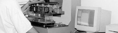
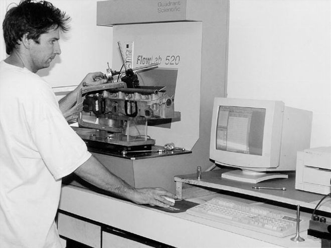
Since our aim with the stock heads is to put together a budget combo, we weren't going for the full-on Pro Stock porting job, but realistic do-it-yourself street porting. Using the equipment at Specialized Motor Service in Riverside, California, I performed all of the cylinder head machining using a Serdi 100 seat and guide machine, while the subsequent port modifications were done at home using an air die grinder and a selection of carbide bits and grinding stones-a true home porting job. All of the flow tests were done complements of airflow expert David Vizard's Quadrant Scientific flowbench, which we used last year in our series on big block heads ("Go With The Flow," Mopar Muscle, January, February, March 1999). We don't expect everyone to have access to a Serdi, let alone be trained to use one, so we'll include the price of the machining at Specialized Motor Service in the porting costs next issue. As for the porting, we'll spill it all in great detail so our results can be duplicated by anyone with the grit to try it. Jerry at Specialized can perform the mods for anyone who'd rather pay-up than break out the grinder.
Take A Seat
Job one in modifying the production smog heads is to cut a performance seat. The valve seat form is critical to the airflow, and is the only factor of consequence at lower valve lifts.
Think about it. Up to approximately .150-inch lift, the biggest restriction to flow is the amount of area the valve has opened. Virtually any port can be upstream of the valve, from a stock 360 smog port to the latest Winston Cup race port, and there will be plenty of air backed-up to the valve waiting to get through. The form at the valve and seat where the air must get passed at lower lifts will determine how much air will actually squeeze through. The seat form is also important as the lift increases, but other factors such as the bowl and port shape will become the major restrictions at higher lifts and influence how much air a set of heads will flow.
Starting at the bottom of the flow curve (low lifts), we were looking to optimize the cylinder head airflow. The two ways to do this are to provide the best seat possible, for the reasons described above, and to increase the amount of area open to airflow.
The amount of area at a given valve lift is first determined by the valve size. A bigger valve means more flow area for the same lift, so the intake valve size was increased from the 360's 1.88-inch diameter to the 340 spec 2.02-inch diameter valve. This is the most common performance intake valve size for small block Mopar heads. A second and not-so-obvious way to increase the opening area is to switch to a 30-degree seat. The geometry of the 30-degree seat provides more opening for the same lift at lower valve openings-23-percent more area at .050-inch lift-with the 30-degree edge decreasing as the valve continues to open, until about .150-inch lift where the open area of the 30- and 45-degree seats converge. Still, with the hydraulic Comp Cams bumpstick we were going to run (Competition Cams 280 Magnum Hydraulic #20-232-4) having a max lift of .480-inch, .150-inch is nearly one third of the total lift curve our engine would see.
We tested the 30-degree seat extensively in our series on big-block heads, and the results were outstanding. The only point to remember is that the change to the 30-degree seat can only be accomplished if going to a bigger valve. Since we were going from the 360's 1.88-inch intake to the bigger 2.02-inch valve, this was a perfect opportunity to make the change. We'd have to cut the seats anyway in the valve job, so the only added cost was to change the face on the intake valve to the new 30-degree seat angle.
However, not every small-block Mopar valve can take the 30-degree face. The stock Mopar valves were a tulip design, in which the head of the valve was cone shaped. These tulip valves, because of the angle of the head tapering up to the stem, can't be cut with a 30-degree angle without making the edge of the valve too thin. Fortunately, many aftermarket valves are made with flat heads rather than the stock tulip shape, allowing the 30-degree angle to be ground on. We went with Milodon's #45640-8 Street stainless steel valves, which are high-flow, flat head valves, offering a flow advantage even if using a conventional 45-degree seat. The seat form used was a 30-degree seat dropping into the bowl with a .150-inch radius to a 75-degree bottom cut just above tangent to the radius.
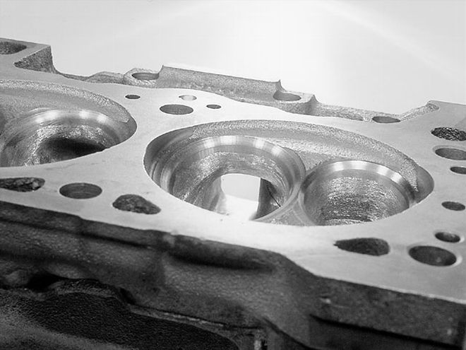
The Shroud of Tourin'
Going to a bigger valve puts the edge of the valve closer to the chamber wall as the valve opens. The proximity of the valve to obstructions is called shrouding. What good is a big valve if it opens right next to the side of the chamber, blocking flow? The move here is to make a machining cut to unshroud the valves. The heads were marked with a head gasket laid in place, scribing the gasket's edge in the vicinity of the valves. A sweeping cutter was used on the Serdi, which cuts the chamber straight down from the gasket line and also has a radius corner leading to a 5-degree topcut that provides a machined surface to locate the enlarged intake valve seat. The process will necessarily lower the valve in the chamber until there is enough machined area on the off-side to accept a seat and minimal top cut. Tricky machining!
Meet Mr. Flowbench
With the machine work done, some port mods were next on the list to get the most from our heads. Not having unlimited time to build the ultimate set of heads, our goal was to go for the big chunks of improvement with "street" type porting, just a little more involved than basic pocket porting. The first step was to set a target and give ourselves a benchmark to judge our progress. It is fairly well established that the "best" of the earlier small block heads are the famous 340 "X" heads, casting #2531894. The 340 T/A heads of 1970 were reputed to have exactly the same ports, but with more meat for future porting. Since the T/A heads are virtually non-existent today, we tested a set of stock 340 "X" heads to see how our 360 smog heads stack up. The results of our flow test are shown in Table 1, Column 1.
No wonder the 340 was such a screamer. These heads flowed better at peak than any of the stock 440 heads we tested last year on the same bench! Flow was better than any of the factory HP Chevy heads on file at Vizard's, with the latest Vortec Chevy heads the only thing that came close. For a factory stock, 30-year-old casting, these 340 "X" heads kicked butt.
Next, we tested the 360 smog head dead stock. The results are shown in Table 1, Column 2. In stock form, the smaller-valved 360 head was no threat to the 340 "X" head, being significantly down in flow from the bottom up through the higher lift ranges. These differences of 10 cfm through the midrange and upwards of 30 cfm up top, showed that we had a long way to go just to equal the excellent 340 head, if we could. Interestingly, if we were comparing to factory small-block Chevy heads, the smog 360s wouldn't have looked so bad.
With the machine work done and the 2.02-inch intake valves installed in the 360 head using our special 30-degree seat, the heads went back to the bench to be retested before any porting work was started. The intakes gave us the numbers found in Table 1, Column 3. The lower range numbers increased dramatically over stock and shattered the figures on the good flowing 340 heads. Remember that the lower lift flow is almost totally regulated by seat form, not the port. Against this highly developed seat form, the 340 heads didn't stand a chance. These numbers, on this bench, to about .250-inch lift and were greater than what would commonly be found on 45-degree Winston Cup race heads. It's all in the seat shape at low lift.
Since the heads went back on the bench raw from the machining operations, the throat area was still restricted below what was cut with the 75-degree throat machining operation. As expected, with the sharp edge where the throat machining met the bowl and the actual throat diameter not being opened up much over the stock 360, top end flow was no better. In fact, it was slightly worse, although peak flow was slightly higher and came in at a lower lift.
Porting For Power
With all of our baseline testing completed, it was time to hit the grinding bench. With the bottom end of the flow curve more than amply handled, our job came down to trying to unlock some flow at the mid- to upper-lift ranges. Since our cam will only open the valves to .480-inch lift, anything above this was strictly academic. It was the midrange numbers that would really make horsepower.
Where to start was obvious, with the sharp machining edge left at the bottom of the throat cut where it meets the bowl. The machining actually left a step where the machining stopped and met with the raw casting below. A few minutes with a carbide bit per port blended this area out, and opened up the bowl area as well. A new flow test gave us the numbers in Table 1, Column 4. At lower lifts, we actually lost a bit of flow, but by .350-inch, the blend increased flow, with a significant advantage of 14.3 cfm by the flow peak at .400-inch lift. We were now past the X heads up to .400-inch, but still down at high lifts.
Our next mod was to blend in the guide boss web, rolling the roof channels around into the bowl by cutting back the web. Only the near (to seat) side of the guide boss was touched in this mod, rolling the web in tight to the guide. Take care not to go deep in the bowl, or where the roof channels originally meet the bowl, or you risk hitting water. The form is shown in photo 9. Retesting the port resulted in the numbers in Table 1, Column 5. The flow improvements became clear at .300-inch lift, and were up markedly throughout the rest of the lift range. We were now well up on the "X" heads through .400-inch lift, with the 340 piece still having an advantage at higher lifts-but the gap was closing.
 To try and raise the cfm level at which the port stalled, the shortside turn was blended around from the area of the bottom cut, around to the port floor, removing a minimum of material to do the job (arrow). The idea is to keep the airflow utilizing as much of the valve as possible, for as long as possible, as port flow and velocity rise to the point where the flow blows past without making the turn down to the valve. It worked, and high lift flow numbers soared.
Looking down along the roof of the intake port of our smog heads, on the high flow, straight side of the port (opposite the exhaust valve), the port has a nasty looking step in the roof, as the guide boss hooks over in the flowpath, and then the roof drops back down into a channel adjacent to the valve. Going back ten years from our '79 smog heads, to the '69 340 "X" heads, we find exactly the same thing. Our next move was to cut this area of the guide boss down, level with the channel, and then blend it in to the port. At the same time, the area was widened between the guide and straight side bowl wall. For fear of hitting water, we didn't attempt to grind the step out, just minimize and blend it, concentrating on cutting back the tail of the guide boss where it hooks over into the straight flowpath. We ended up with the flow in Table 1, Column 6. Our peak flow was now past that of the 340 "X" head, but was occurring .050-inch sooner, before the port became overworked and stalled. Both heads peaked at about 220 cfm, and then stalled and stabilized at 210 cfm. Our port was working so well down low that the peak hit much sooner.
With one side of the roof done adjacent to the guide, we were compelled to clean up the other side for aesthetic reasons. We blended the dogleg side of the roof in the vicinity of the guide boss, and also blended the guide boss itself. Even with the heavy-handedness held to a minimum, the move appeared counter productive, as flow was not significantly improved, and our flow peak was sliced off the top of the flow curve. We lost 8 cfm at .450-inch lift before stabilizing roughly the same 210 cfm we were at before. What happened? The peak could have shifted to an intermediate point that we didn't record, such as .425-inch lift. Our peak in test 5 was at .400-inch lift, while in test 6 it moved to .450-inch lift. In either case, a peak was reached, then flow stalled and quickly dropped back down. If indeed the lost flow peak was nowhere to be found (we didn't check), a likely culprit was that we were now encouraging air around the dogleg side of the bowl. As this flow front enters the bowl and curves around the chamber from one side, the air collides with the main airstream coming from the opposite side. This costs flow-especially when the air is moving at high velocity at, or near, max flow.
In any event, our port, like the 340 port, was reaching a peak and then dropping off to about 210 cfm. Even though this was happening at high lifts, higher than we would see with our cam, there was still something to be learned. We decided that the port itself may be a restriction. The most constricted part of the port runner is just in from the entrance, at the pinch-in for the pushrod holes. This area will net very little, if any, improvement in an otherwise unmodified head. Once the rest of the port, specifically the bowl and the transition from the port into the bowl, are working well, it may be time to open things up at the inlet.
Our next step was to hog out the port opening to match the Fel-Pro gasket from the gasket set that came with our engine. If you just flare the edge of the port out to the gasket line, the port opening area won't really increase at all. We opened the manifold face well into the port (up to 1-inch) where there was a mismatch. Most material was removed from the pushrod side, blending back from the manifold face all the way around the corner at the pushrod constriction, opening the constriction about .060-inch in the process. Our hunch proved correct, with the numbers shown in Table 1, Column 8. Flow was increased, starting surprisingly low in the curve, at .200-inch lift, with peak flow up 5 cfm over our previous best, and most of the high lift numbers up 10 cfm over our previous test. The port would now stabilize 5-6 cfm higher after stalling, at 216 cfm. Peak flow was 6.6 cfm up on the 340 "X" head, and occurred 0.1-inch of lift sooner. A much fatter curve.
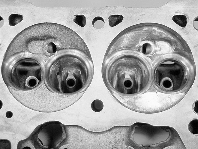 The last step was to polish the chamber. This removes potential hot spots from sharp machining edges aiding in detonation resistance, minimizes carbon build-up, and helps retain more heat in the combustion process for a slight improvement in combustion efficiency. The edges where the deshrouding cuts meet the chamber (arrows) were contoured into the chamber. Flow was largely unchanged.
We were fat in the street lift range, and downright obese down low, but greedy for more. If only we could get a touch more flow through that valve before the port stalls. What we learned on the big block heads is the importance of the form in the area of the shortside turn. We need to use as much of the valve as possible, even as the velocity of the air barreling down the port wants to skip across the shortside of the valve and crowd the long side. These small block heads have a relatively nice form in the shortside-for a production head-but we figured there was some flow to be had here. When we did the bowl blend modification in Column 3, the handwork at the shortside was just to blend out the ridge left by machining. No blending was done around the corner and into the port floor.
At this point, the corner around the shortside still had numerous casting irregularities, so these were mildly blended out from the valve side, around the turn, and into the port floor, keeping the form round, from off the seat, gently flattening out to the port floor. A minimum of metal need be removed in the process.
It worked! The flow increased substantially up top, and to an extent down low, as seen in Table 1, Column 9. Peak flow catapulted to 236.5 cfm, at .450-inch lift. These heads built lots of flow, and built it outstandingly quickly. Stall flow went up to nearly 225 cfm, 15 cfm higher than the 340 "X" head, and nearly 10 cfm higher than our previous test. The excellent 340 "X" head's numbers were bested throughout the flow curve, and in the lift ranges that matter in our application, by a substantial amount. There may have been more flow left to be found in the shortside, but we were satisfied. Our work on the intake port was done, with our objectives more than met.
As a final step, the combustion chamber was smoothed and polished to help lessen the onset of preignition and detonation by removing hot spots and sharp edges. The sweeping cut in the chamber on the intake side takes out a small section of the spark plug boss, which needs to be blended smooth. We also blended the Serdi machine sweeping cuts into the chamber as outlined in photo 14. The flow was essentially unchanged, save for a few cfm unexpectedly gained down low, Table 1, Column 10.
In the February issue of Mopar Muscle, we'll return with the exhaust port modifications as well as a complete cost breakdown. Can this be done at home on the cheap? We think so and we'll prove it! Sure, the porting takes some skill and a couple of weekends, but if you want to go fast for a minimum of dollars spent, you have to pay the piper, be it through know-how, or time, or both.
Table 1: Intake Port Modification Sequence Col. 1*Col. 2*Col. 3Col. 4Col. 5Col. 6Col. 7Col. 8Col. 9Col. 10* 360 Head:360 Head:360 Head:360 Head:360 Head:360 Head:360 Head:360 Head:StockStock30-Throat/BlendGuideRadiusGasketShort sideFullyLift340 "X"360degreeBowlGuideBoss RoofIntakePortradiusPorted/(in.)HeadHeadseatsBlendBoss WebBlendValveMatchblendPolished0.0000.00.00.00.00.00.00.00.00.00.00.02515.012.920.119.419.618.518.219.021.020.60.05031.529.838.137.937.537.438.438.039.339.80.{{{100}}}58.350.275.874.273.470.772.673.274.477.10.15091.679.5112.3106.8107.9105.0108.0108.0109.4111.80.{{{200}}}124.7112.6140.0132.6134.3133.5134.7137.8136.7137.30.250152.5142.2162.0157.0158.7158.4159.6{{{164}}}.5161.7162.60.{{{300}}}172.0164.8179.8177.4180.1179.2180.1185.3184.2185.50.350193.6183.5193.2197.8200.0200.1201.3209.5207.0206.60.400208.3188.2194.4208.7215.1217.6216.4227.6225.0224.80.450215.4193.8190.0197.9210.7222.8214.3225.2236.5236.40.500221.0192.6190.9197.0205.4211.0208.4218.9227.8228.00.550220.7190.3191.4197.0204.9209.0209.3215.9224.0224.00.{{{600}}}210.0189.1187.5196.6205.6209.0209.0216.3224.7224.3*Figures plotted on graph "Intake Flow Comparison." Flowed at 28-inches H2O on Quadrant Scientific Flowlab 520