Special thanks to Billy Godbold at Competition Cams and Mike Golding at Crane Cams for their assistance in the preparation of this article.
Camshaft issues always sell magazines, and readers always ask for more. Just when we thought you were sick of it, our most recent readers' poll demanded even more info on how the camshaft works. That's why this story will offer more on the hows and whys of camshaft specifications than any other in recent memory. This time we'll count on you to know the basic definitions of terms such as intake opening, duration, and lift as we go into the theory of how each aspect of cam design tends to affect engine power.
Car magazines have published rain-forest-loads of issues dealing with camshafts. Why? Because the cam is one of hot rodding's most common, most visceral, and most baffling upgrades.
Intake Opening
Looking at the intake valve first, its opening point is critical to vacuum, throttle response, emissions, and gas mileage. At low speeds and high vacuum conditions, premature intake opening during the exhaust stroke can allow exhaust gas reversion back into the intake manifold, hurting the intake pulse velocity, and contaminating the fresh intake charge. A late-opening intake gives smooth engine operation at idle and low rpm, plus it ensures adequate manifold vacuum for proper accessory operation (assuming the other three valve opening and closing points remain reasonable).
As rpm increase, air demand is greater. To supply the additional air and fuel, designers open the intake valve sooner, which allows more time for the intake charge to fill the cylinder. With an early-opening intake valve, at high rpm the exiting exhaust gas also helps draw the intake charge through the combustion chamber and out the exhaust-that's good for purging the cylinder of residual gas, but it also increases fuel consumption by allowing part of the intake charge to escape before combustion and can make for a rough idle.
Camshaft: Intake Closing
The intake closing point has more effect on engine-operating characteristics than any of the other three opening and closing points. The earlier it occurs the greater the cranking pressure. Early intake closing is critical for low-end torque and responsiveness and provides a broad power curve. It also reduces exhaust emissions while enhancing fuel economy.
As rpm increase, intake charge momentum increases. This results in the intake charge continuing to flow into the combustion chamber against the rising piston far past BDC. The higher the engine's operating rpm, the later the intake closing should be to ensure all the charge possible makes it into the combustion chamber. Of course, closing the valve too late will create significant reversion. It's a fine balancing act.
In a perfect world, the optimum intake closing point would occur just as the air stops flowing into the chamber; would get the valve seated quickly and not waste time in the low lift regions where airflow is minimal and there is no compression building in the cylinder; wouldn't be so fast that the valve bounces as it closes, allowing the charge to escape back into the intake port and disturb the next charge; and, in hydraulic street cam applications, would ensure the closing ramps are not so fast that they result in noisy operation.
Exhaust Opening
Overall, the exhaust valve opening point has the least effect on engine performance of any of the four opening and closing points. Opening the exhaust valve too early decreases torque by bleeding off cylinder pressure from combustion that pushes the piston down. Yet the exhaust has to open early enough to provide enough time to properly scavenge the cylinder. An early-opening exhaust valve may benefit scavenging on high-rpm engines because most useful cylinder pressure is used up anyway by the time the piston hits 90-degrees before BDC on the power stroke. Later exhaust valve opening helps low rpm performance by keeping pressure on the piston longer, plus it reduces emissions.
Exhaust Closing
Excessively late exhaust valve closing is similar to opening the intake too soon-it leads to increased overlap, allowing either reversion back up the intake, or the intake mixture to keep right on going out the exhaust. On the other hand, late closing events can help purge spent gasses from the combustion chamber and provide more vacuum signal to the intake at high rpm. Early exhaust closing yields a smoother operating engine. It does not necessarily hurt the top-end, particularly if it's combined with a later intake valve opening.
As engine operating range increases, designers must move all the opening and closing points out to achieve earlier openings and later closings, or design a more aggressive profile to provide increased area under the curve without seat timing increases.
Lobe Centerline
Tailoring the valve opening and closing points on an actual camshaft is accomplished by varying the lobe centerline location, changing the LDA, and refining the profile shape itself. We'll consider changing the centerline location first. Advancing the cam moves both the intake and exhaust centerlines an equal amount, resulting in earlier valve timing events. Engines typically respond better with a few degrees of advance, probably due to the importance of the intake closing point on performance. For racing, advanced cams benefit torque converter stall, improve off-the-line drag-race launches, and help circle track cars come off the corner.
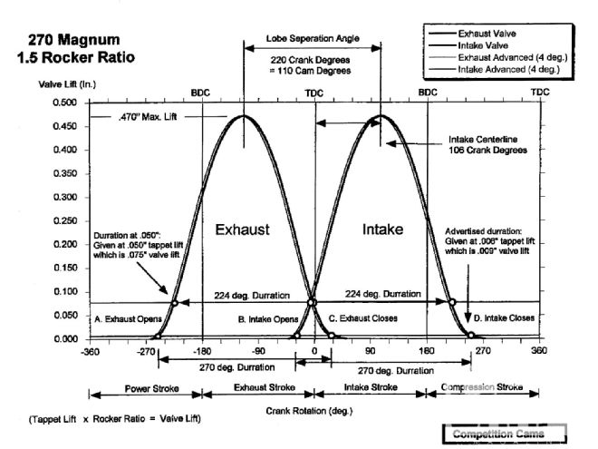 This cam is ground with a 110-degree lobe displacement angle, but 4 degrees advanced (106-degree intake/114-degree exhaust lobe centerlines, heavy lines). If the installer advanced it another 4 degrees (8 degrees total, light lines), the intake and exhaust centerlines move to 102 and 118 degrees, respectively, but the LDA is still 110 degrees.
Cam companies often grind their street cams advanced (4 degrees is typical), which allows the end-user to receive the benefits of increased cylinder pressure, yet still install the cam using the standard timing marks. One exception is Crane's CompuCam series, which varies because of the vacuum signal requirements of the ECMs it's designed to operate with.
Lobe Displacement Angle
Although the installer can advance and retard the lobe centerlines, the displacement angle between the centerlines is ground into the cam at the time of manufacture and cannot be changed by the end-user. Narrow LDAs tend to increase midrange torque and result in faster revving engines, while wide LDAs result in wider power bands and more peak power at the price of somewhat lazier initial response.
A street engine with a wide LDA has higher vacuum and a smoother idle. On the street, LDA should be tailored to the induction system in use. According to Comp Cams, typical carbureted, dual-plane manifold applications like 110-112 LDAs, while fuel-injected combos want slightly wider 112- to 114-degree LDAs. Fuel-injection doesn't require the signal during overlap that carburetors need to provide correct fuel atomization, and most computer controllers require the additional idle vacuum that results from decreased overlap.
Bracket racers with higher stall-speed converters, high compression, single-plane intakes, and large carbs usually want 106-110-degree LDAs.
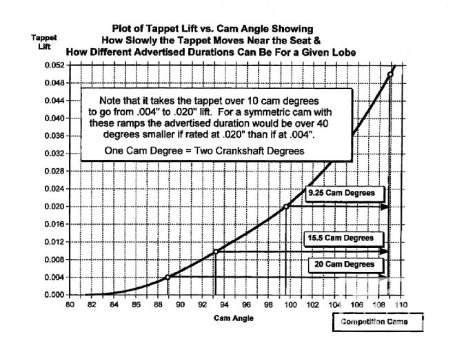 Off the valve seat, relatively small changes in the advertised duration lift rating point can cause a big change in the cam's published advertised duration numbers.
Engines equipped with blowers or turbos, or used primarily with nitrous oxide, typically work best with wider 110- to 116-degree separations. Race engine speeds have increased over the years causing a corresponding upward creep in LDA and duration.
Duration
Duration has a marked effect on a cam's power band and driveability. Higher durations increase the top-end at the expense of the low-end. A cam's "advertised duration" has been a popular sales tool, but to compare two different cams using these numbers is dicey because there's no set tappet rise for measuring advertised duration. Measuring duration at 0.050-inch tappet lift has become standard with most high-performance cams. Most engine builders feel that 0.050 duration is closely related to the rpm range where the engine makes its best power. Typical daily driven, under-10.25:1-compression ratio street machines with standard-size carbs, aftermarket intakes, headers, and recurved ignitions, like cams with 0.050-inch durations in the 215- to 230-degree range if using a hydraulic grind, or 230- to 240 degrees with a solid.
When comparing two different cams, if both profiles rate the advertised duration at the same lift, the cam with the shorter advertised duration in comparison to the 0.050 duration has more aggressive rmp. Providing it maintains stable valve motion, the aggressive profile yields better vacuum, increased responsiveness, a broader torque range, and other driveability improvements because it effectively has the opening and closing points of a smaller cam combined with the area under the lift curve of a larger cam.
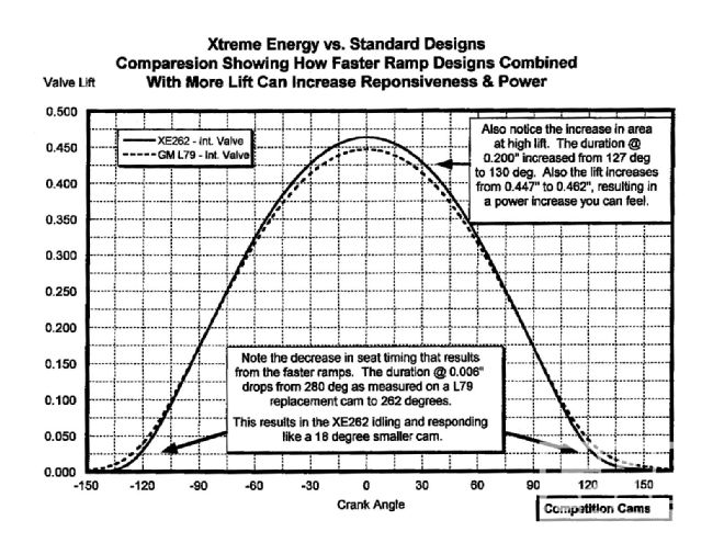 Aggressive lobe ramps allow the valve to reach maximum velocity more quickly, generating more area for a given duration.
Engines with significant airflow or compression restrictions like aggressive profiles. This is due to the increased signal that gets more of the charge through the restriction and/or the decreased seat timing that results in earlier intake closing and more cylinder pressure.
Big cams with more duration and overlap allow octane-limited engines to run higher compression without detonating in the low- to mid-range. Conversely, running too big a cam with too low a compression ratio leads to sluggish response below 3,000 rpm. Follow the cam grinder's recommendations on proper cam profile-to-compression ratio match-up.
Lift
Another method of improving cam performance is to increase the amount of lobe lift. Designing a cam profile with more lift results in increased duration in the high-lift regions where cylinder heads flow the most air. Short duration cams with relatively high valve lift can provide excellent responsiveness, great torque, and good power. But high lift cams are less dependable. You need the right valvesprings to handle the increased lift, and the heads must be set up to accommodate the extra lift. There are a few examples where increased lift won't improve performance due to decreased velocity through the port; these typically occur in the race engine world (0.650-1.00-inch valve lift). Some late model engines with restrictive throttle-body, intake, cylinder head runner, and exhaust flow simply can't flow enough air to support higher lift.
Besides grinding a lobe with more lift, you can increase the lift of an existing cam profile by going to a higher rocker arm ratio. For example, small-block Chevys where the cylinder head runners are not maxed out may benefit from moving up from the stock 1.5:1 ratio to 1.6:1 rockers. But going up more than one tenth in rocker ratio can lead to trouble; there's a limit to how fast you can move and accelerate the valve before the valvespring can no longer control the system. If a profile was a good design with 1.6:1 rockers, it'll probably be unstable with 1.8:1 rockers. The correct solution is to design the profile from the ground up for use with high-ratio rocker arms.
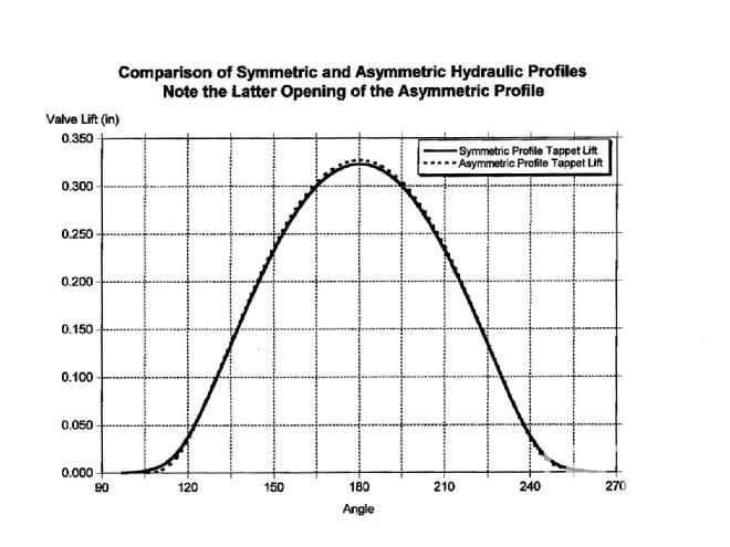 In an effort to increase the engine's power potential, designers often skew the cam's timing points. This requires an asymmetric design. The later opening asymmetric lobe improves low-end performance without sacrificing total area under the curve.
Overlap
Duration, lift, and LDA combine to produce an "overlap triangle." The greater the duration and lift the more overlap area, LDAs remaining equal. Given the same duration, LDA and overlap are inversely proportional: Increased LDA decreases overlap (and vice versa). More overlap decreases low-rpm vacuum and response, but in the midrange overlap improves the signal provided by the fast-moving exhaust to the incoming intake charge. This increased signal typically provides a noticeable engine acceleration improvement.
Less overlap increases efficiency by reducing the amount of raw fuel that escapes through the exhaust, while improving low-end response due to less reversion of the exhaust gases back up the intake port; the result is better idle, a stronger vacuum signal, and improved fuel economy.
Due to the differences in cylinder head, intake, and exhaust configuration, different engine combos are extremely sensitive to the camshaft's overlap region. Not only is the duration and area of the overlap triangle important but also its overall shape. Much recent progress in cam design has been due to careful tailoring of the shape of the overlap triangle. According to Comp, the most critical engine factors for optimizing overlap include intake system efficiency, exhaust system efficiency, and how well the heads flow from the intake toward the exhaust with both valves slightly open.
Asymmetric Lobes
In the past, both the opening and closing sides of a cam lobe were identical. More recently, designers developed asymmetric lobes, wherein the shape of the opening and closing sides differ. Asymmetry helps optimize the dynamics of a valvetrain system by producing a lobe with the shortest seat timing and the most area. The designer wants to open the valve as fast as possible without overcoming the spring's ability to absorb the valvetrain's kinetic energy, then close the valve as fast as possible without resulting in valve bounce. There are many different theories about how to design the most aggressive, stable profile.
Asymmetric lobes can better tailor the cam to specific cylinder head idiosyncrasies. To optimize airflow, some heads may need a slow opening intake, or a slower-closing exhaust.
Hydraulic lifters can provide quiet valvetrain operation only if the closing velocity is kept below a certain threshold. However, the opening velocity can be higher and still provide quiet operation. Almost all modern hydraulic profiles have some asymmetry.
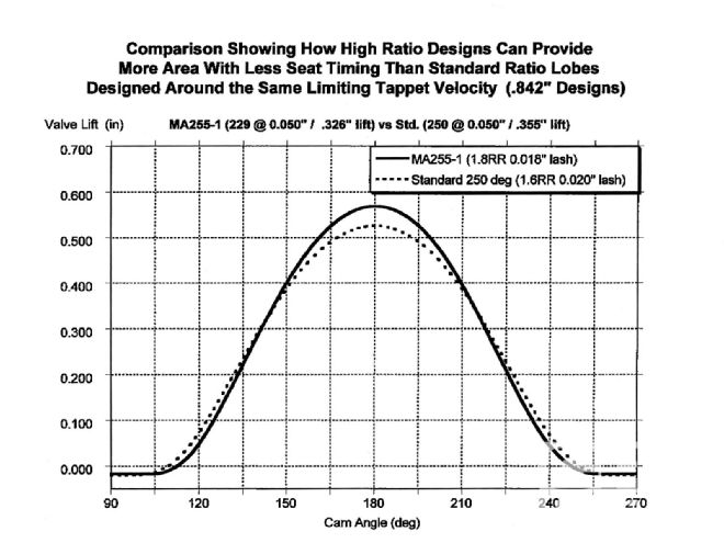 A cam lobe specifically optimized for high-ratio rocker arms can provide more area with less seat timing than standard ratio lobes designed around the same limiting tappet velocity. Both these lobes were designed for GM's typical 0.842-inch tappet foot diameter.
Dual Pattern Cams
If an engine has equal airflow potential on the intake and exhaust sides, a single-pattern cam is sufficient. When the airflow differs markedly between the intake and exhaust, a dual-pattern cam should be used to balance flow through the engine. In street applications, they help compensate for a full exhaust system. The amount of difference between the intake and exhaust lobes is based on the cylinder head's characteristics, the intake and exhaust system design, and whether the engine is normally-aspirated, blown, or nitrous-injected.
A recent trend in dual-pattern street cams is to use unique-profile intake and exhaust lobes. Not only does the duration and/or lift of each lobe differ, but the overall lobe shape is specifically optimized for use on the intake or exhaust side. Comp's Xtreme Energy series is an example of this approach. The intake profiles minimize seat timing and maximize area, and the exhaust profiles promote excellent scavenging, increased signal, and maximum airflow.
Tappet Dancing
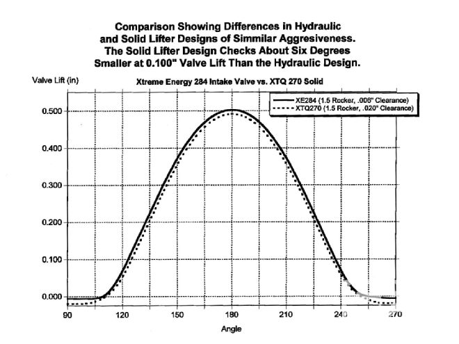 Due in part to its lifter's hydraulic action, don't compare a hydraulic grind directly against a solid grind. This illustration shows the differences between hydraulic and solid lifter profiles of similar aggressiveness. The solid lifter design checks about 6 degrees smaller at 0.100-inch valve lift than the hydraulic.
Flat Tappets
Hydraulic flat-tappet camshaft and lifter systems are the most popular configuration for street applications. They provide quiet operation, low maintenance, easy installation, great response, and good power. But hydraulics can "pump up" at high rpm, leading to rapid power loss caused by valve float.
Solid flat-tappet lifters offer a stiff system that can more easily maintain control at high rpm. They require periodic valve lash adjustments, but these can be minimized with good rocker adjustment locking devices. For street use, the crossover point between hydraulic and solid lifters is somewhere between 6,000 and 7,000 rpm, depending on the engine's specific valvetrain configuration and weight.
Mechanical cams usually need about 8-10 degrees more duration to have a comparable power band to a hydraulic lifter cam in the same engine. Also, a mechanical cam's gross valve-lift figures don't include lash, so the recommended lash must be subtracted to come up with the theoretical valve lift.
With flat-tappet cams, the maximum velocity allowed by the tappet before the contact point between the tappet and lobe skates off the edge and causes failure is directly proportional to the tappet diameter. A larger diameter tappet allows the use of a profile with higher maximum velocity. Profiles designed with higher maximum velocity can have more area and more lift for a given duration than similar profiles with less maximum velocity. Most GM applications use a 0.842-inch lifter foot diameter, but Fords and Chryslers use 0.875-inch and 0.904-inch, respectively. This gives these engines a theoretical advantage (albeit at the cost of a slightly heavier lifter) when restricted to a flat-tappet profile if the profile is ground to take advantage of it.
Roller Tappets
Tappet diameter becomes irrelevant with roller lifters. Solid roller lifters allow much higher velocities than flat-tappets and can tolerate the increased spring forces necessary to maintain valvetrain control with these extremely aggressive designs. The typical powerband of flat tappets is 3,000- to 3,500-rpm wide, yet roller lifters usually have a 4,000-4,500-rpm wide band. This is because rollers can hold the valve on the seat longer, then open it quicker. However, the initial departure from the valve seat is slightly slower than a flat tappet because of geometrical limitations. At some point, as rollers are designed for quicker and quicker acceleration off the seat, the designer must go to an inverted ramp profile. There is a limit to how much inversion is possible before the flanks become too difficult to grind. Overall, the increased area permitted by the roller's higher average velocities more than compensates for its slower initial acceleration. Lifter wear was the main drawback to rollers, but new lifters are being introduced that provide greatly increased durability. Currently, the main drawback is cost.
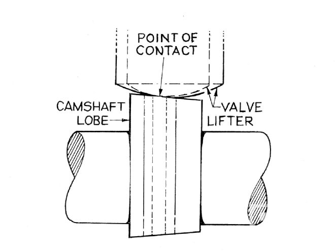 A larger diameter flat-tappet has a greater contact area on the cam lobe than one of smaller diameter. The greater contact area permits the design of a more aggressive profile without decreasing its reliability.
Hydraulic roller lifters provide many of the same advantages as solid roller lifters. However, they are more rpm-limited than hydraulic flat tappets. This is due to the hydraulic roller's higher overall weight, which makes it hard to utilize the more aggressive potential of rollers and maintain stability over 6,500 rpm without relying on very high spring forces that tend to collapse the hydraulic plunger. Further development may lead to improvements in this area, but cost still remains a problem.