
1.Bad GroundsIt's standard: You overkill the positive side of the 12-volt circuit and ignore the ground circuit. Basic electrical circuit design requires a complete path back to the battery through the ground circuit, and if it has high resistance, then the electrical device will operate poorly.
Bad grounds happen everywhere, but the worst case is when guys relocate the battery to the trunk, run a nice, thick multi-strand cable from the battery to the starter solenoid, then merely bolt the ground cable to the trunk floor or other easily accessible spot and leave it at that. A voltage-drop test (see page 58) on that ground circuit will probably reveal an inexcusable 1.5- or even 2-volt drop across the ground side of the circuit. The starter may crank when it's cold, but not once everything warms up (remember, resistance increases with temperature). The fix is to either run a large ground cable all the way up to the engine, or a large ground from the battery to the frame and another from the frame to the engine.
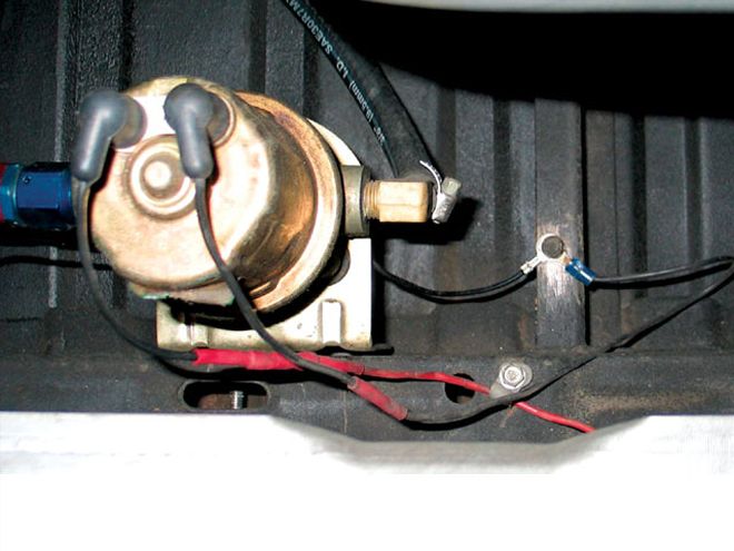
Another common grounding failure is an electric fuel pump pulling 4 to 5 amps. We often see pumps wired with a small, 14-gauge positive cable and further crippled with a corroded piece of piano wire for a ground. Improve the ground circuit with a larger 12-gauge wire and ensure that the ground circuit offers no more than 0.1-volt drop and the fuel pump will run much more efficiently.
The most dangerous bad ground comes from weak or small-wire grounds between the engine and the chassis and between the chassis and the body. These create resistance that can quickly overheat and in extreme cases begin to melt and catch fire. It sounds implausible, but keep in mind that the ground circuit must complete the current flow, so the ground side must always be as bulletproof as the positive side of the circuit.
2. Makin' The HookupEvery auto parts store in the country offers those cheesy crimp connectors with the little plastic sleeves that are supposed to provide a great connection. The problem is that these temporary fixes soon become permanent. Certainly one of the least effective electrical connectors has to be that one that pinches two parallel wires, hoping to make a connection. If you find one of these connectors in your car, cut it out immediately. And when you get them in the box with a new electrical goodie-especially a nitrous system-chuck them as far as you can.
There is some controversy over the proper way to make an electrical connection. Fans of solder will tell you that it prevents corrosion, but its detractors say it's too brittle and will eventually fail immediately adjacent to the connection. The problem with crimp connections-even when protected with shrink wrap-is that they are sources for corrosion. Either way, the following steps outline the right way to perform an electrical connection.
3. Alternator Charges Less Than Your GirlfriendOften the alternator is blamed for poor charging when the problem is actually bad wiring or connections. So try this quickie test. With the engine running, check the voltage at the output terminal of the alternator; on Terry McGean's Camaro, we found a high 15.7 volts. Next, measure voltage at the battery; McGean's was barely 13.5 volts, a loss of 2.2 volts in a circuit that should lose no more than 0.4 to 0.5. The Camaro suffered from multiple broken strands in the charging wire and several corroded connections. We added a large-diameter charging wire from a Painless Wiring high-amp alternator kit and improved the connection between the battery and the junction block using a MAD terminal block. Voltage drop across the circuit improved to 0.5 volt. Furthermore, by reducing resistance in the charging circuit, the alternator output voltage dropped back to a more reasonable 14.7 volts while voltage at the battery measured 14.2 volts.
4. Ganged WiresLet's hope the positive battery post on your musclecar doesn't look like a bowl of spaghetti. Combine that with a typical unsealed battery and the connections quickly become corroded and nasty. The solution is to move all those wires off the positive battery post and onto a separate terminal block. MAD offers an inexpensive one (PN CN-1) that can accommodate several 8-gauge wires to power multiple accessories. This is also a great idea for an underhood power source for cars with the battery in the trunk. This block can be used to power up an MSD, electric fans, an A/C, and solenoids for nitrous along with at least a dozen other ideas. Hide this under the fenderwell and carefully route your wires and you'll be amazed how clean your engine compartment will become.
5. Hot-Start ProblemsMany slow cranking problems can be traced to high-resistance cables. Using high-quality MAD or Painless battery cables is the obvious solution. The MAD cable is impressive 1/0 gauge multi-strand copper conductor that is also double insulated. If the starter just grinds slowly, this is a voltage-drop problem. But if you've got the typical GM problem of the starter not engaging properly in a hot-soak condition, the cause is a major voltage drop across the solenoid-engagement circuit. The fix is as simple as using a Ford-style external solenoid in a kit from either MAD or Painless. The idea is simple: Mount the solenoid away from exhaust heat, which radically reduces the voltage drop across the solenoid circuit. Both kits also supply a shunt that connects the solenoid battery cable terminal to the small trigger post. Another advantage is that if you use one of these kits with a trunk-mounted battery, the only time the battery cable downstream from the solenoid is "live" is when the starter is engaged. This is a small point, but worthy of consideration from a safety standpoint.
6. Erratic Gauge PerformanceHave you ever had a set of electric gauges change readings when you turn on the headlights? This is caused by a poor ground circuit, a power circuit that cannot handle the additional load, or both. Most '60s cars provide power for the wiring harness through a tortuous path leading up to the fuse box under the dash. There are plenty of opportunities for power loss and voltage drops along the way.
The quick fix is to improve the ground path between the instrument cluster and the battery by adding those ground straps you threw away between the engine and the firewall. Then add one or two between the instrument panel and the firewall and see if the performance improves.
7. Relays RaceIf you've ever run a wire from that poor overloaded fuse box to power up an electric fuel pump, or if you've used a large wire from the battery to a switch and then to a heavy-duty electrical load like an electric fan, there's a better way to go than large clunky switches. Relays are a handy heavy-duty switching device that can be activated by a very low voltage switch. In fact, computers use relays to control high-current-draw items like electric fans and electric fuel pumps.
Here's how relays work. Let's say you're going to bolt on a 20-amp electric fan. You could run a large 8-gauge wire from the battery all the way up to a switch under the dash and back to the fan. Instead, mount a relay between the fan and the battery. This creates a shorter power path from the battery to the fan through the relay. Then you can use any light-duty switch to control the fan. Relays also work well for reducing the voltage drop on '60s GM car headlight circuit. Mount a pair of relays near the headlights and eliminate the long power path through the headlight switch. This shorter path through the relays puts much more voltage to the headlights, making them much brighter.
8. Underdash PowerHow many wires do you have jammed into that overloaded fuse box under the dash of your street machine? Most musclecar electrical systems were never intended to handle great electrical loads. So when you start jamming more wires into those "switched" and "unswitched" fuse-box positions, this greater load could eventually cause problems. Not only that, but it just looks cluttered.
The solution is to use a couple of MAD's terminal blocks, one for constant battery power and the other for "switched" power when the ignition key is on. The key is to mount two terminal blocks on a common aluminum mount located under the dash near the stock fuse block. The battery live terminal can pull power directly from the junction block off the battery under the hood. The second terminal can be switched using a relay triggered by a "switched" terminal on the fuse block.The battery live terminal should be protected with a fusible link located under the hood. Now you can bundle all those cockpit accessories to source power from these two terminal blocks and not overload the stock fuse block. If you really want to be safe, design a clear plastic cover for the terminal blocks so there's no way to accidentally short the block to ground.
9. One-Wire AlternatorsThere's confusion about aftermarket one-wire alternators versus typical three-wire alternators. A typical production-style three-wire alternator uses a voltage sensing wire connected to a main power distribution point in the wiring harness. This "sensing wire" allows the voltage regulator within the alternator to read electrical system voltage resulting in proper voltage delivery to the wire harness. A three-wire alternator also has a special switched "turn-on" wire, and this wire can also be used to operate a warning light at the dash. A one-wire alternator requires internal voltage created by the spinning alternator to trigger or start the charging process since it does not have a voltage-sensing trigger connection. When the engine is started, a one-wire alternator must achieve a certain speed in order to reach that internal voltage. Once that occurs, the one-wire alternator will begin charging and will charge even at very low engine speeds. This means you must simply rev the engine above a given rpm (usually around 1,500 depending upon the pulley ratio) before the alternator will begin to charge.
According to a rather substantial treatise on one-wire vs. three-wire alternators on MAD's Web site, the voltage drop from the alternator to the battery with a long wire can compromise the performance of the one-wire alternator compared to a three-wire. This is why MAD recommends using the GM 10Si or Cs130 alternators, even in many Ford applications. This is not a condemnation of the one-wire alternator. But if you want the most from an alternator, the three-wire version is slightly more efficient.
10. Fusible LinksWhat the hell is a fusible link? Think of it as a safety net for your electrical system. Most domestic cars from the mid '60s through the '70s source all the electrical power for the car (except for the starter) from either the main charging harness or, in the case of GM cars, from the smaller wire pulled directly off the positive battery terminal. To protect the wiring harness, most of the car companies used an inexpensive wire called a fusible link that is designed to melt when the current demand exceeds a given level, like from a direct short. This protects the wiring harness from damage, but also immediately disables the car. Often, ignorant wire hackers set the car up for a potential wiring meltdown and subsequent fire by eliminating this fusible link.
If your GM car is now equipped with a fusible link, you can purchase an inexpensive replacement from MAD in 12-, 14-, 16-, and 18-gauge sizes depending upon the circuit they are protecting. It's also a good idea to protect individual circuits with their own fusible links. Fusible links are sized to protect a circuit four wire sizes larger. Also remember that larger gauge numbers indicate a smaller wire. So a 14-gauge fusible link would protect a circuit using larger 10-gauge wire.
Voltage-Drop TestThis one simple test will tell you more about any specific electrical component than any other test you can perform. The idea is to measure the amount of voltage that is lost while the circuit is in operation. What we're really doing is using the voltmeter to learn the amount of resistance in the circuit without having to remove any components, but current must be flowing at the time of the test.
To begin, set the multimeter on the lowest voltage setting-most often the 20-volt scale. Let's say we're going to test the amount of resistance in the negative battery cable. A high-quality cable with a good connection should only have about a 0.1-volt drop across its length. To test it, place one probe on the battery end of the negative cable and the other probe on the end of the cable where it's bolted to the engine. Disable the ignition system so the engine doesn't start, then have a helper crank the starter while you watch the multimeter. During cranking, current will flow through the circuit, and the voltmeter will indicate a voltage. If you measure more than 0.1 volt, there is high resistance in the circuit. You can also narrow your focus as much as you wish. For example, to find the resistance in just the connection between the battery and the cable, place one probe on the battery post and the other on the cable end, then crank the starter. If you see more than 0.05 volt then the connection is poor.
A higher voltage measured with the voltage-drop test means greater resistance. Increased resistance means the electrical system is delivering less power (current) to the load, like the starter motor, headlights, or electric fan. The more power you can deliver to the load, the more efficiently it will operate. It's just that simple.
VOLT-DROP VALUES Component Acceptable Volt Drop Battery Cable 0.1 to 0.2 volt Switch 0.2 to 0.3 volt Alternator output to Battery* 0.4 to 0.5 volt Wire to Electric Fuel Pump 0.1 to 0.2 voltThe voltage-drop spec between the alternator and the battery is the textbook maximum. However, many factory wiring systems get around this spec by using a main "buss-bar" for central power distribution. This version routes the alternator output and the voltage-regulator sensing wire directly to the buss-bar. In this layout, electrical system performance relies upon voltage level at the buss-bar not at the battery or alternator. This means a voltage drop greater than allowed by the above spec may not indicate a problem. Chevy musclecar-era systems were equipped with this layout with a higher acceptable voltage-drop spec. There's more specific information on this topic at www.madelectrical.com.