When the season is over, or when something breaks inside your rearend during the season, it is time to disassemble, repair or rebuild, and then reassemble your rearend. There are methods and tools available that will make your job go smoother, with better overall results. The tips presented here may help prevent costly mistakes.
When disassembling your rearend, make sure you note the condition of all the parts. When first draining the rearend grease, run it through a filter to see if there are any telltale metal bits or pieces that may indicate a part failure.
Look over the gear wear pattern as well as the bearing play and any obvious cracks in the housing that may only be seen from the inside. Now is the time to decide whether to replace the centersection, a right- or left-side bell, or one of the axle tubes.
After complete disassembly, clean the centersection and all of the gears thoroughly. Again, when cleaning, note any strange wear patterns or signs of stress in the housing, bearing hangers, and so on.
Once all of the parts have been cleaned and inspected, we must select the type of pinion bearing we are to use. There are standard or special low-friction bearings available. These LF types actually reduce rotational friction and therefore reduce the amount of horsepower needed to turn the rearend. This increases the power to the rear wheels and would be a good choice based on cost versus benefits.
We are now ready to assemble the pinion. We press the new bearing onto the front of the pinion shaft. Now add a small amount of antiseize to the threads of the pinion and install the pinion washer and the Posi-Lock Nut by hand. Leave this un-torqued for now.
Next, install the nose roller bearing at the rear of the pinion shaft. The pinion is now assembled and ready to install into the centersection.
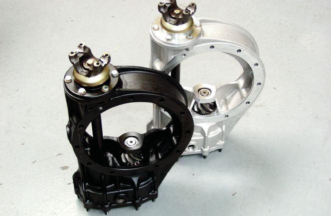 The centersections and the bells are now available in black anodized, plain aluminum, magnesium, or titanium. The black coating reduces retained heat, which is the enemy of bearings, gears, differentials, and so on.
Decide on which type of lower shaft, or jack shaft as it is sometimes called, you will use. There are several choices, including solid, gun-drilled, or the type that is hexed at the rear for an oil pump drive. That third type is also available in either solid or gun-drilled and all three can be polished. The Lower Shaft takes two bearings, the front lower and rear lower shaft bearings.
Note: It is advised, if space allows, to run the rearend oil pump off the pinion shaft if possible. This slows down the speed of the pump by the same amount as the gear ratio of the rearend.
Now put the centersection in an oven and heat to a temperature of 250 degrees F—not to exceed 300 degrees F—for at least 15 minutes. A pair of heavy welder’s gloves will be needed to place the centersection into and out of the oven. This heats and expands the bearing holes for easy insertion so that after the section cools, the pinion and jack shaft bearings will be held tight.
After it has been sufficiently heated, take the centersection out of the oven and lay it on its side. Install the pinion assembly with the nose roller bearing installed on the pinion shaft. Make sure you get the bearings to bottom out in the bearing bores. Because the casing is still hot, the bearings may not seat all of the way and we want to make sure the bearings are fully seated.
Next we install the lower shaft, and slide the proper front and rear bearing in the lower shaft bearing bores while again making sure they are fully seated. Now, let the centersection sit and cool off.
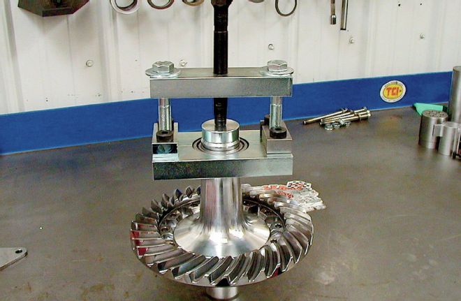
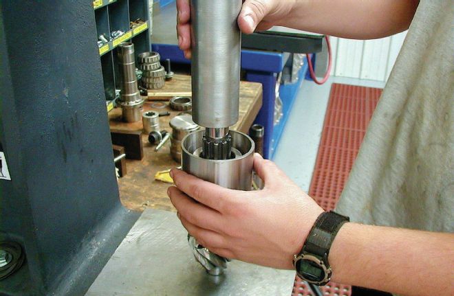 Special tools are used to press the bearings onto the pinion shaft. These assure that the bearing goes on straight and is properly seated. Throughout this process, note that using the right tools will make your rebuild project more successful.
After cooling, the centersection is placed in a vise that has aluminum jaws. Install the rear cover studs if these are being replaced or have been removed on disassembly. At each threaded hole we push a 5/16 steel ball to the bottom of the hole before installing the stud. This is so that the stud will seat tightly against the ball and not stop at the untapped bottom portion of the threaded hole. Use red Loctite, putting a small amount on the hole thread before screwing in the studs.
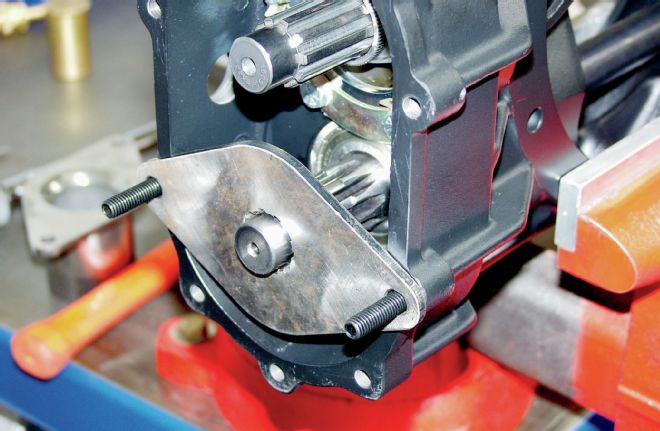
Install the pinion retaining plate. This will involve using three locking tabs, and six 3/8x16x1-inch bolts. Use antiseize on all of the bolts and torque them to 35 lb-ft. Do not use Loctite here because you will bend the Locking Tabs over the bolt heads to secure them. The retaining plate also holds the rear lower shaft bearing in place.
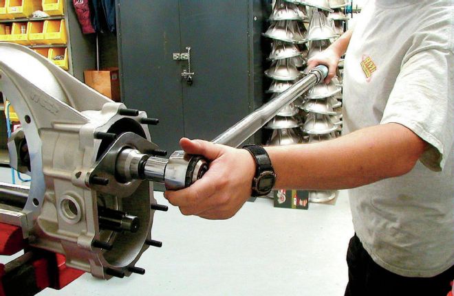 The pinion nut is held in place using a special tool that is held by the cover studs. Then the pinion shaft is rotated to obtain the proper torque on the nut. You will need a long torque wrench to attain the proper loading in the nut.
Next torque the pinion nut. The reason we installed the cover studs first is that they will hold the specially designed pinion torque tool. This tool holds the nut as we turn the pinion shaft from the rear to a torque of 150 lb-ft for the low friction bearings, or 25 inch/pounds rotational resistance for the standard Timken bearings. Now install the posi-lock cap over the pinion nut. This keeps the pinion nut from backing off. Then install the yoke spacer onto the lower shaft to prevent the yoke from pressing on and ruining the seal.
A Yoke Seal is then installed in the seal plate and it is held in place by a new retaining ring. Install the O-ring in the groove and attach the aluminum seal plate to the front. Fasten this plate using six Cat washers and six 3/8x16x11/4-inch bolts. Before tightening the plate, slide the drive yoke into the seal, placing a small amount of oil on the Yoke surface first.
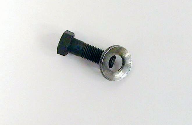
 This little tool holds the jack shaft while you tighten and torque the yoke nut.
Apply blue Loctite onto the bolts and then torque them to 35 lb-ft. With the drive yoke in place, put a small bead of silicone around the end of the lower shaft and the front edge of the yoke. This serves to seal between the spline grooves to prevent oil leakage. Then the 3/8x24x11/4 bolt and drive yoke retaining washer are installed and torqued to 55 lb-ft.
You will need to decide which type of differential to use. There are many choices available and no matter which one you end up with, the process of the build is the same. Let’s just say we are going to use a Spool, by far the cheapest of all and the most common.
 The washers used to bolt the ring gear to the differential use special Bellville washers that are cupped and act as a type of locking washer. Be sure to use the correct thread locking liquid and put the Loctite in the threaded hole and not onto the bolt or stud.
We are ready to install our ring gear onto the differential, in this case the spool. We hand prepare the surface (using very fine emery cloth, sand paper, or a honing stone) on the back of the ring gear. Clean thoroughly after preparation. The ring gear is threaded for 12 bolts that use Bellville washers. These special washers are cupped and provide a “locking” effect.
Red Loctite is applied to the threads in the ring gear holes before inserting the ring gear bolts. Applying the Loctite to the holes instead of the bolts is done on purpose to prevent the possibility of seepage of Loctite onto the surface of the ring gear between the gear and the differential, which would happen if applied to the bolts. If anything gets between these two parts, the gear will not run true to the pinion and there will be trouble. Torque the ring gear bolts using a crossing pattern in three steps, first to 35 lb-ft, then to 45 lb-ft, and finally to 55 lb-ft.
Now we can put our bells and axle tubes together. All tubes should be scribed so that they will be installed properly. When using cambered tubes it is critical to line up the tubes properly to prevent rotation of the tubes that will create unwanted toe in the rear wheels. This is very important to get right.
If you are going to run the tube seals, this is the time when you would install them into the axle tubes. Push them out toward the snout end and away from the bell end. This is so they will not be near the bell end of the axle tube as it is inserted into the hot bell.
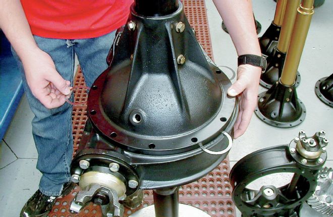
 Note the special stand that holds the axle tube. The snout is screwed into the stand. Using this tool puts the parts within easy reach. You can build one of these at your shop.
The assembly of the bells is fairly simple. You have a left- and a right-side bell. Each bell is scribed with a 0- and 2-degree mark. The heavy welder’s gloves are again needed. Place the bells into the oven and heat to 250 degrees F for 15 minutes. Once they are up to temperature, take one out, noting left from right. Make sure you put the left axle tube in left bell and the right axle tube in right bell while making sure the alignment marks are in line.
When using cambered axle tubes, the snouts are of an opposite angle side to side. Accidentally reversing the tubes would reverse the intended camber angle. A negative 1.5-degree tube properly mounted on the right side would still be a negative 1.5-degree snout when mounted on the left side where we really need the left side to be a positive camber.
After a few seconds of cooling, the tubes will become firmly married to the bells. At this point turn the axle tube and bell assembly over and install the new bearing race into the bell, making sure they are fully seated. Then let the entire assembly cool.
If we have a new bell or axle tubes, you can now drill and tap the bells and tubes to permanently attach them. We will be using 3/8x24-inch bolts for this. Now is the time when you push the tube seals back into the tube toward the bell end. Upon completion, we will make sure the seal is between the two sets of axle tube bolts.
 Spacer shims of 0.0100-inch thickness are placed between the centersection and the right bell to adjust for crush clearance. This is a trial and error way to obtain the correct shim spacing behind the differential bearing to arrive at 0.010-inch crush when tightening the bell to the centersection.
After the holes are drilled and taped and the edges of the holes are cleaned up, push the seal all the way back to the bell end of the tube. Install the outer bolts (ones toward the snout) using red Loctite, and then slide the tube seal out against the outer bolts while you install the three inner bolts, adding a small amount of red Loctite. Torque them all to 35 lb-ft. Now the tube seal is sandwiched between the two sets of bolts and this will keep the seal from moving in or out in the tube.
Now take the left tube and bell and stand it on end with the tube snout down. We thread it into our specially made stand built to hold the axle tube. It has a threaded collar that we screw the tube into and that is welded to a steel wheel. Now we have a base we can use to finish assembling the rearend.
Some of the most critical steps are coming up. We now have the left bell on the bottom with the differential bearing race facing up. Install the wear pad in the machined bore in the left bell and run it all of the way out for now. We are now going to work on getting the lash and crush spacing correctly set. The lash is the spacing between the pinion gear and the ring gear and the crush is the preload on the differential bearings.
 Once the rearend has been bolted together and re-checked for gear lash, a final adjustment might need to be made. That means the carrier bearings must be pulled. This tool pulls the pressed-on bearings without causing damage.
This is a very important step. This part of the build may take the most time because you may have to press bearings on and off and add and subtract shims to get the right numbers. One trick you can use is using “set up” bearings. These are temporary bearings that have been lightly honed and enlarged on the inside surface so it will slide easily over spool. The final assembly will require that the new bearings will need to be pressed on.
As a starting point, we begin with a 0.020- to 0.025-inch stack of shims on the bottom of the spool behind the bearing and then slide a setup bearing on. Now we will set the spool in the left bell, leaving the bell O-ring seals out until final assembly.
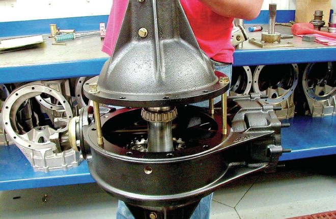
Now we will place our centersection onto the left bell. By pressing down hard onto the spool, centered on the taped bearing race, and holding the pinion still, turn the spool back and forth and you can estimate the lash. We want to feel around 0.010 or so of lash between the pinion and the ring gear. If it is too tight or too loose you would add or remove from the shim stack on the spool setup bearing until you get it close.
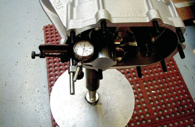
 Another unique tool is this pinion Flag Tool. It is specially designed to provide a surface to rest the dial indicator on to check gear backlash. The distance from the center of the pinion shaft to the point where the indicator lies is the same as the distance to where the gears mesh. This way you get a true lash measurement as if you had measured between the actual gear teeth.
It is now time to place shims onto the top of the spool and under the bearing. Adding shims equaling about 0.060 inch will put you close. Now slip your other setup bearing on the spool.
Place the right bell and tube over the spool and set it on the centersection. If the bell fits down on the spool bearing without rocking you will need to add more shims to the top. What we want is for the bell to end up approximately 0.010 inch off the centersection before we tighten the centersection bolts.
To get there, start out by placing 0.010 inch of shims at equal spacing in three places around and between the centersection and bell. If you can press down on the tube and bell with the shims in place and it does not rock, we may need to add (and not remove) internal shims to achieve a 0.010-inch crush spacing.
Add or remove shim spacing under the bell until the bell starts to rock. Then add or remove small increments of the shims until there is no rocking and the shims fit the gap like a feeler gauge. Measure the final thickness of the bell shims and find the difference between their thickness and 0.010 inch. If the bell spacer shims are more than 0.010 inch, remove that difference from the shims behind the spool bearing to lower the bell to a 0.010-inch gap. If the bell spacer shims are less than 0.010 inch, add the difference to the shims behind the spool bearing to bring the gap up to 0.010 inch.
Once we have installed the correct amount of crush shims, we will check the gear lash. For backlash we will tighten the right bell to the centersection and use a lash tool attached to the pinion shaft. We need to see 0.010-0.012 inch of lash as we rotate the pinion gear against the ring gear. To adjust this lash, we will be moving small amounts of the spool bearing shim stack from the right to the left if the lash is too little, or from the left to right if the lash is too much.
 We use the centersection bolts to guide the bell into place. With the O-rings in place, mismatching the bell to centersection might cause leaks later on.
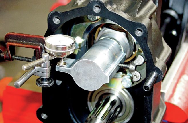
We can now install our dial indicator to check the pinion to ring gear lash. The tool mounts onto one of the cover studs and we then slide a flag tool onto the pinion shaft. We can check the lash to the thousands by rocking the pinion shaft back and forth, making sure to check the lash in several different places on the pinion gear. This means we check the lash in one position, then rotate the pinion shaft 90 degrees and do it again all of the way through 360 degrees.
This is a trial and error method that can take some time, but is essential for optimum performance. Once we have arrived at the correct shim spacing, we will press the new differential bearings onto the spool leaving the shim stacks as they ended up. We will go back and reassemble the bells and centersection and redo the lash measurement process all over again.
Most of the time it will come out the same, but if not, we may have to make a final fine adjustment by adjusting the shim spacing. Be sure to use a special bearing puller tool if you need to remove a pressed-on bearing to prevent damage to the bearing.
For final assembly, unbolt the rear and remove the right bell and centersection and place the bell O-rings in their grooves, first on the left bell. We need to use a light film of silicone around the mating surface of both of the bells and centersection. Place two of the centersection bolts into the centersection and slide the centersection down onto the left bell. Press the centersection down and take the two bolts out and place them in the right bell.
Now slide the right bell down over the centersection using the bolts to line it up. Install the 10 thru-bolts and two stud bolts and torque them all to 40 lb-ft using the crossing pattern.
As a final step, we will adjust the wear pad we installed in the left bell. Screw the wear pad, or thrust block as it is also called, in until it just barely touches the back of the ring gear and back it off 1/8 turn. This should equal between 0.010 and 0.015 inch of clearance. The purpose of this pad is to support the ring gear on the back side of the rearend (opposite the pinion gear) if the front of the ring gear tries to move away from the pinion gear.
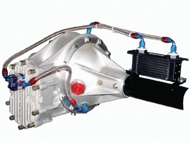
Install the rearend and fill it with the recommended amount and type of lubricant while also checking for leaks. By using proper assembly techniques and using quality parts, your racing rearend should provide many races of reliable performance before your next overhaul. If using a locker differential or one of the traction sensing types, you can reduce the heat in the rearend by using a rearend cooler. This helps especially if your racing involves long runs. Just as in brakes, heat is the enemy for rearends too.
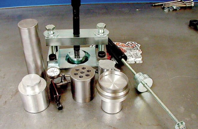 Contact your rearend supplier to purchase a kit for use in disassembling and reassembly of your rearend. Using the right tools can make your project easier and more successful.