You learn things when you build a car, and if it takes you long enough, you’ll learn enough to improve on your original plan by the time you get to the later stages. This is part, but not all, of what accounts for having to do everything three times. In our case, that is nowhere truer than in wiring up Scarlett’s LS3 416 to the FAST XFI computer and ignition box.
FAST generously provided not only the ECU and spark box but also the wiring harnesses to connect them to the engine and each other. We quickly ran into a very basic problem, however: a lack of space. Since mounting the computer under the hood seemed unwise, we initially put it beneath the center console only to discover that it interfered with the controls for our Vintage Air system. Mounting it under the passenger-side dash was a non-starter also because of the A/C system, and screwing it to the kick panel left something to be desired aesthetically. After making sure it would clear our Corbeau seats, we ultimately turned to mounting the ECU under the driver’s seat and the spark box under the passenger’s.
Unfortunately, moving them that far away from the engine bay left us without enough length for the wiring harness to reach the engine. Rather than extend each and every wire that went to the engine, we took a little inspiration from Mark Stielow’s book Pro Touring: Engineered Performance, where he used a military grade circular connector to route all engine wiring through a single connector. After wandering around on the Internet trying to decipher all the military specifications (and failing), we settled on Deutsch-compatible Delphi HES Harsh Environment connectors. Sealed both by an O-ring inside as well as a rubber wire seal on the outside, the circular HES connectors can hold as many as 47 pins and are designed, as their name suggests, for places that are hard on connections. They are also easily adapted for bulkhead use (buy the seal and nut) making them a natural fit for our application. We sourced them from Waytek, our primary source for OEM-type wiring components, as well as adhesive-lined heavy-duty shrink tube in a number of sizes.
While simpler than the military connectors, there was still homework to be done in finding which connector to use. HES connectors come in two different shell sizes: 18 and 24, with 24 being the larger. Needless to say, the larger the shell size, the more contacts it can hold. Each connector uses a mix of different pin sizes: 1mm, 1.6mm, and 2.4mm. Each of these pin sizes then come in male or female, as well as different sizes based on the gauge wire that you intend to use and type of wire covering (GXL/SXL or TXL). Since we’re using mostly 18-gauge GXL wire for all but the largest pins (for which we’ll be using 10-gauge wire), we selected 1 and 1.6mm pins for that wire. The rubber wire seal also varies based on wire covering, blue is for TXL and orange is for GXL/SXL. While the Waytek website doesn’t describe all of this on the product page, there’s a link to the catalog page with a helpful chart, and there’s also a link to a multi-page product description from Delphi that’ll clear up any remaining questions.
Once we located a mounting point for our connector, we then routed all the engine wiring from the ECU and ignition box into the connector using zip ties (which we’ll later replace with harness tape) to bundle the different groups of wires—coils, injectors, sensors, etc.—together. Under the hood, we effectively did the same thing, but typically built the individual harnesses from the connector to the sensors or other terminals from scratch and routed them through heat shrink tubing so we could seal it all up. We used every pin on our 47-pin connector—and got every wire on the engine, except major ground straps, through it.
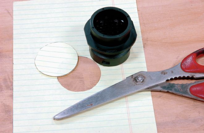
01. We started by using the body of our connector and a sheet of paper to create a template to help us locate a spot big enough to make the hole, and then to mark it. Note that there’s a flat on part of the circle: the flat keeps the receptacle from turning when the plug is locked into place on it.
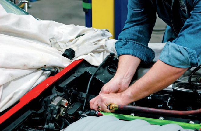
02. We found an unused vacuum port on the driver-side firewall, near the throttle cable, and opened it up to the correct size and shape with a hand grinder. Before cutting, we made sure both connectors would clear the throttle cable on both sides of the firewall.
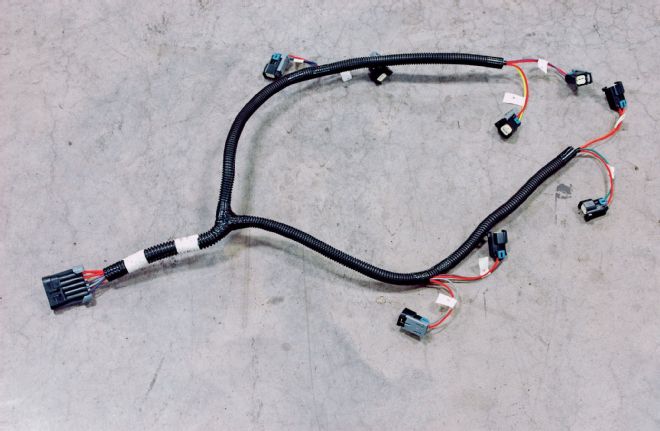
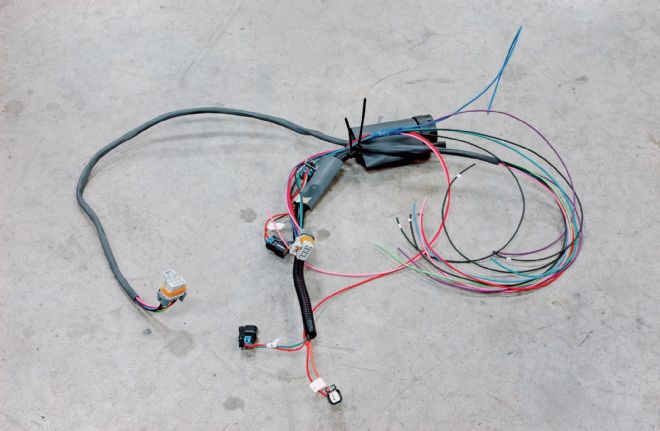
03. The clean, well-built injector harness provided by FAST. While we were able to leave part of it intact, we had to remove the harness plug and connect those wires to our multi-pin circular connector instead.
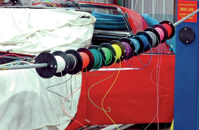
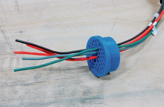
04. If you’re going to build a harness, or even subharnesses, you’ll need a lot of wire on hand, and it’s smart to have every color used in the factory harness so that you can match colors and minimize confusion later. Remember to plan for future serviceability. We ordered a broad selection of 18-gauge wire from Waytek Wire. This is just a portion of our order.
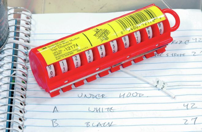
05. You don’t have to be a genius, but you do have to pay attention, and that includes marking the wires. We used 3M numbering tape to label each one, generally with the pin number from the HES connector, and wrote down everything we did in a spiral-bound notebook with a separate page for each group of wires (injectors, sensors, etc.).
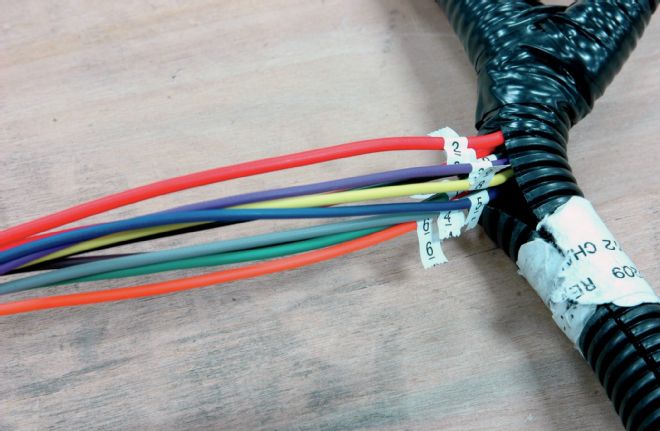
06. We labeled the wires as far back as possible from the end we were going to terminate, a practice we arrived at the hard way. Since you always plan to have excess wire—much better than being too short—if the numbered label is too close to the end you’ll wind up cutting it off and having to relabel the wire.
07. Whenever possible, we used heavy-duty adhesive heat shrink to group the wires together on each subharness, such as this one for the passenger-side coils. This adds extra protection to the wires and keeps the wires grouped together with the rest of the wiring for whatever sensor/plug/etc. they’re going to.
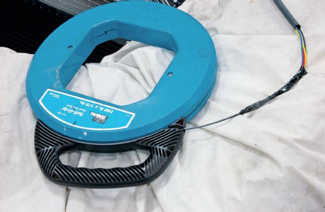
08. In order to get the wires through fairly narrow lengths of heat shrink, we had to resort to this steel fish tape and lubricant from Ideal. Just bundling the wires together won’t always work; at a certain point friction wins.
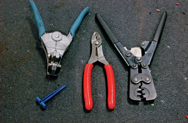
09. The most important tools we used (left to right): an Ideal wire stripper, which will give you better control and save a lot more time over standard plier-type strippers; a pair of crimping pliers; a Packard metri-pack crimper; and (bottom left) the fragile plastic pin removal tool, of which you should have several. There is an HES-specific set of crimpers that are in the few hundred dollar range, but if you’re careful the Packards will work fine. If you’re not careful you shouldn’t be doing this to start with.
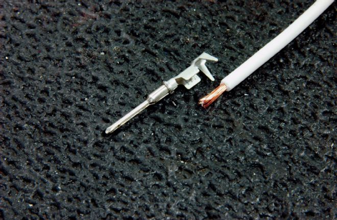
10. Like many other terminals, the HES pins are designed to be crimped to the wire for the connection and to the insulation for strength. This is where the Ideal strippers come into play, since you want to strip the insulation precisely to get the maximum contact between wire and terminal.
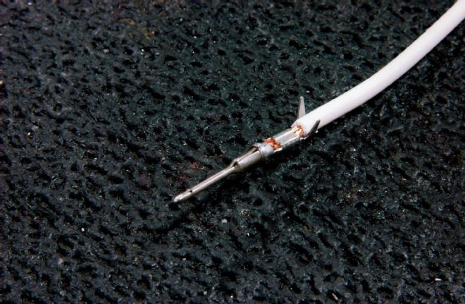
11. The first crimp is to the wire, which we made using the metri-pack crimpers, and it should roll the metal of the connector around the wire from either side.
12. Once the first crimp is made, the remaining wings on the terminal should be tightly wrapped around the insulation. If that part of the crimp is not kept round, it may be difficult to insert the pin into the connector, and nearly impossible to remove it later. Ask us how we know.

13. Not exactly what you want to see when you look inside your car, but we learned that hanging the wires off the T-top made it a little easier to keep a visual on what we had done and what remained to be dealt with. Once the wires were pinned into the connector we used zip ties to bundle them together by application. For final assembly we’ll use harness tape and cover them with a protective braid or conduit.
14. For both the plug and receptacle of the circular connector, the wires pass through this rubber wire seal before seating in the plastic body of the connector. Like the housing itself, each hole has its contact number molded into it. Start to pin out the connector from the inside first: the connector is pretty dense, and once you have a good numbers of wires in place getting to the inside is very difficult.
15. An inauspicious beginning for the engine harness, which here has only the injector and coil subharnesses in place. We routed each wire through a collar of heat shrink, terminated it, and mounted that pin in the connector. If we didn’t have the correct terminals (there are at least three different types of metri-pack connectors used in the sensors and coils) we cut the wire extra-long and made a note to order the terminals. In addition to individual wire markers, we marked each subharness with a piece of painters tape and a written description.
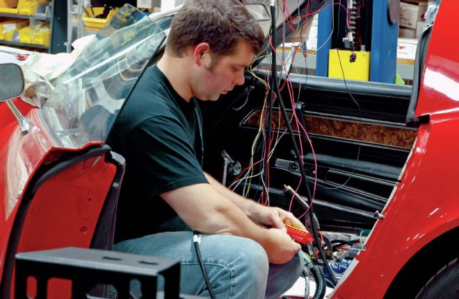
16. We made sure to label wires as we pinned out the subharness. This is tedious work, and you cannot make a mistake, which means checking and rechecking constantly. We worked slowly, building harnesses as we went, and it took about four work days to get everything laid out and get both connectors completely pinned out.
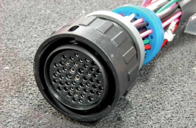
17. As is typical of multi-pin connectors, the male connector (which Delphi calls the plug) uses female terminals, and vice versa. Note both the different size terminals, and the individual numbers marking each hole. These are a lifesaver—but make sure you know which hole goes with which number prior to inserting the terminal.
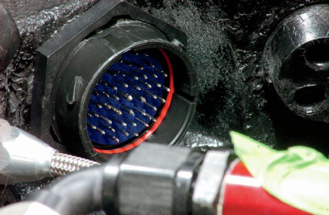
18. The female receptacle completely pinned out. Note the O-ring seal, as well as the different size slots into which the plug fits. It only goes in one way, and you’ll want to make sure you have both the plug and housing oriented correctly when you start plugging in wires. Getting it done only to learn you have to twist it upside down to plug it in doesn’t sound like a lot of fun.
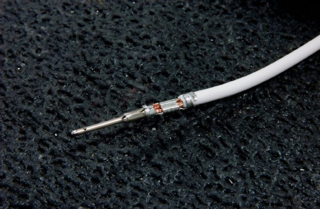
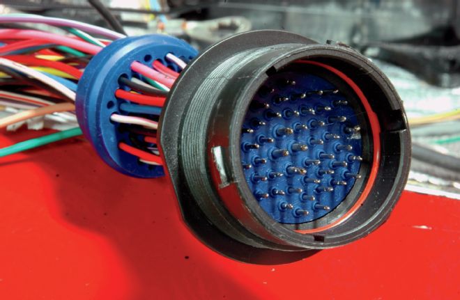
19. Once the connector is completely pinned out—and we used all 47 pins, with no need for the plugs we ordered—the blue wire seal will have to be carefully pushed and prodded down into position. Note the ribbed locking collar, which is how the plug locks into the receptacle when they’re plugged into one another.
20. The plug with all wires pinned in place and the wire seal snugly seated in place. The molded in arrow on the locking collar lines up with a similar arrow on the body of the plug as well as on the receptacle. The collar is then turned to lock it all into place.
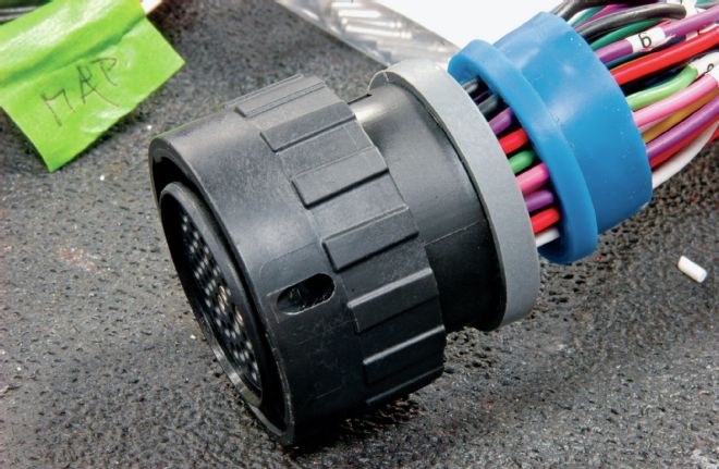
21. Here’s the finished receptacle in place on the firewall. To use it as a bulkhead connector all you need to do is slip a seal over the threaded part of the body, push the connector through the bulkhead, then use the plastic nut to hold it in place. The nut has slots to clear the locking lugs on the connector before engaging the threads.
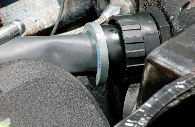
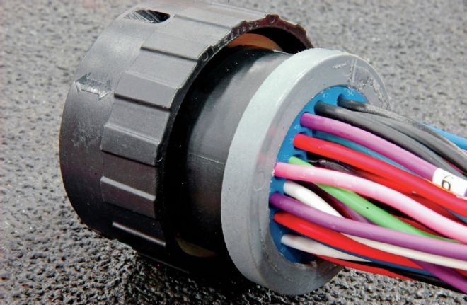
22. With all the wires routed into the underhood connector, it plugs and locks into place on the firewall-mounted connector. Here, the heat shrink has yet to be shrunk into place, which will seal everything up.