Those who follow such things will tell you that the best designs not only perform well, but that they just flat look good too. There are certain designs that will always be timeless, like the near-perfect form of a P-51 Mustang warbird or the shape of a 1955 Chevy taillight. Such a case could be made for the cross-ram manifold. The idea was simple enough. It's really nothing more than a horizontal tunnel ram. There are plenty of early examples of the tunnel ram. The Chrysler-bred Ramchargers designed a crude but effective tunnel ram out of lengths of rubber hoses fitted to a large box on top of which was bolted a couple of carburetors.
But it wasn't until the mid-1960s when that idea finally caught hold. In 1966, Trans-Am took off and suddenly short stroke 302ci small-block Chevys were in need of eight barrels worth of air and fuel. But these little motors also needed torque to pull them off the corners and that demanded intake manifold runner length. The current eight-barrel intake manifolds lacked runner length, so an enterprising engineer, probably in the employ of General Motors, created the cross-ram manifold. All he did was lay the runners down across the top of the manifold so that the added length didn't pop through the hood. With that elegant solution, generations of hot rodders were entranced with the idea.
That lust for an exotic eight-barrel induction has never really gone away. Combine this with a better understanding of engine tuning and the effects of a pair of big carburetors on a small displacement engine and we have circled back to resurrect an old-yet-new Offenhauser manifold on our 1955 Gasser project. (As luck would have it an Offy manifold base (PN 5893), a manifold top (PN 5903), and the appropriate linkage kit (PN 5902) were waiting for us on a back shelf. You can still order these part numbers from Offy but they may be on back order.) Form demands that we not place a mundane single four-barrel on such an aggressive nose-high Gasser so the cross ram seemed a natural, if for no other reason than Gassers never came with such an animal. But function demands that beyond killer looks our eight-barrel adventure must also work. So that became our quest and the not-small effort that ensued.
Street Rodder Editor Brian Brennan wanted one of Offenhauser's cross rams to put on top of his retro 327 small-block being installed in the 1955. Ironically, among the dusty piles of tooling in Offy's backroom were the exact pieces necessary to produce one of these discontinued manifolds. The die was, ahem, cast and the result is what you see here. But that was just the beginning. Most rodders would be content to add a couple of early Holley four-barrels or perhaps even a pair of early Carter carburetors, but while this is a classic retro ride, there aren't any rules that we had to follow the norm. The best way to add a little 21st century flash was to integrate a pair of electronic throttle bodies using FAST's EZ-EFI system. Usually the FAST system is designed to operate with just one four-barrel throttle body, but FAST offers a system with a piggyback harness to connect to the second slave throttle body with injectors only. This adds a wire harnesses to the top of the manifold but that was relatively easy to disguise to maintain the look of a typical 1960s Gasser induction. We added a retro-looking fuel line and some slick throttle linkage pieces and we were in business. Follow along as we chronicle the crossover of a 1960s manifold into a current piece of fuel injection technology. Don't forget to stay tuned for the buildup of our Retro-Tech 327, which will grace the pages of this magazine in the next couple of months. We will once again be combining both old and new technology in our 327 Gasser motor. Who says you can't teach an old dog a few new tricks?
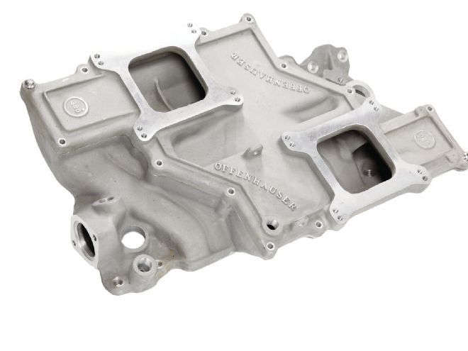 1. The original cross-ram manifold for the small-block Chevy was designed by Chevrolet engineers and Offenhauser merely used that as a loose pattern for their own version.
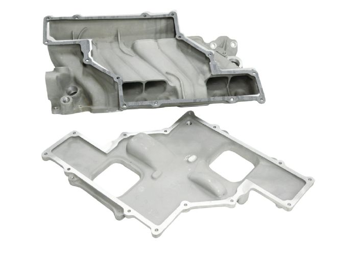 2. With the lid removed, note the two protrusions that are not for clearance but instead are flow directors to enhance mixture distribution. Even with these additions, these manifolds still suffer from inconsistent distribution.
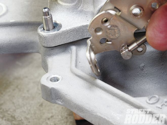
 3. Offenhauser supplied a linkage kit that is still available specifically for this manifold.
 4. One improvement over the GM design is the Offenhauser cast-in boss to mount the throttle linkage. There are also two pipe thread bosses for a PCV valve.
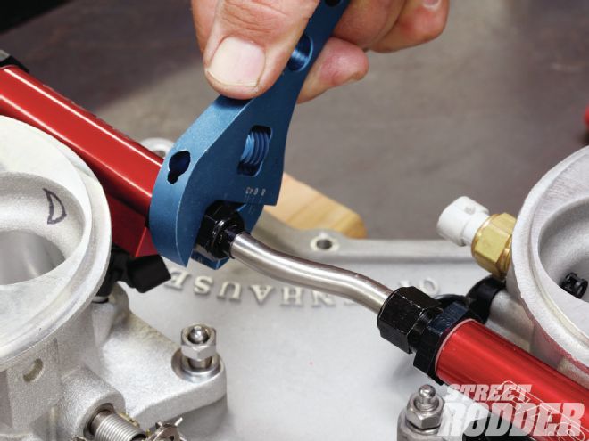
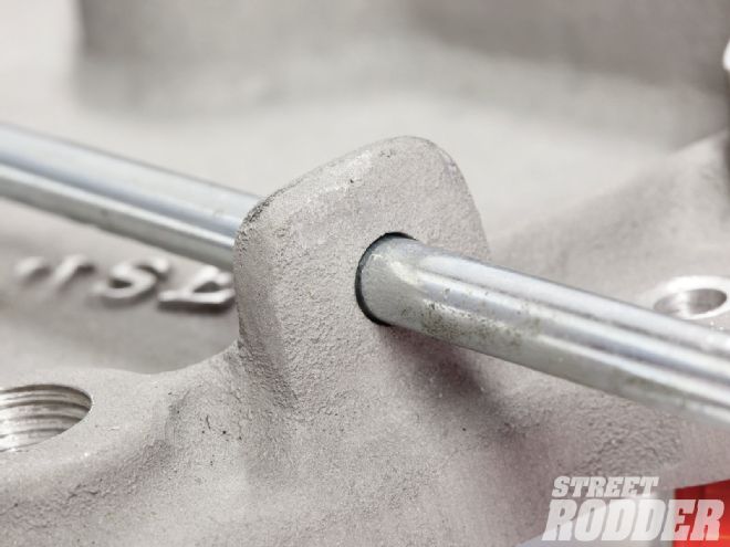
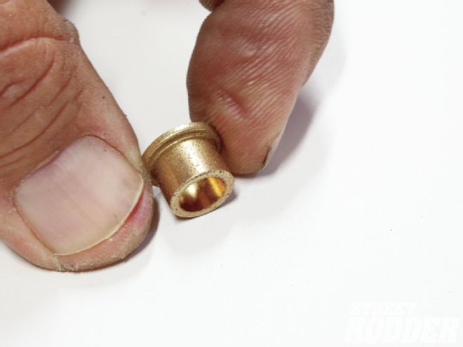 5. The standard Offenhauser linkage arrangement was a bit “loose”, so we found this Oilite bronze bushing at McMaster-Carr. We then machined the manifold for an interference fit the outside diameter of the bushing.
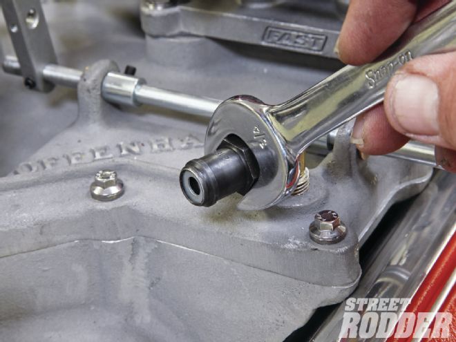
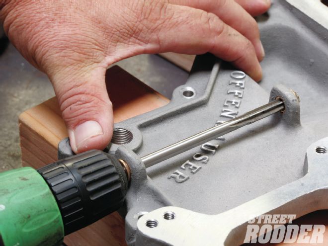 6. We then reamed the inside diameter of the bushing to fit the existing linkage rod. This dramatically improved linkage performance between the dual throttle bodies so that opened at the same time and rate.
 7. On the passenger-side throttle body, we had to bend the lower portion of the linkage 90 degrees to clear the bottom of the manifold. Or, if you prefer, you could remove this portion of the linkage arm.
8. McMillan Speed & Fab created this short transfer line between the two throttle bodies using 3/8-inch stainless tubing and tube nuts from Earl’s.
7. On the passenger-side throttle body, we had to bend the lower portion of the linkage 90 degrees to clear the bottom of the manifold. Or, if you prefer, you could remove this portion of the linkage arm.
8. McMillan Speed & Fab created this short transfer line between the two throttle bodies using 3/8-inch stainless tubing and tube nuts from Earl’s.
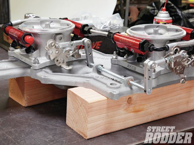 9. We installed the two FAST EZ-EFI throttle bodies and mocked up the linkage and fuel lines to make sure everything fit properly. The throttle linkage is now precise. The FAST dual-quad system uses a master/slave throttle body strategy. This means that one throttle body has most all of the sensors that are required to run the engine, while the other throttle only has injectors installed.
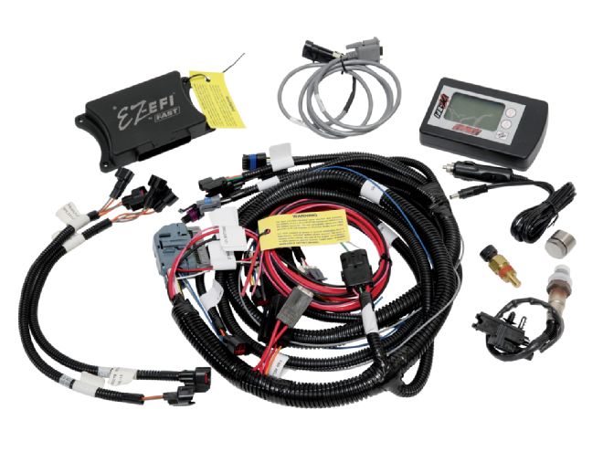 10. This is the wiring harness, O2 and water temp sensors, dual-quad adapter harnesses, computer, and the handheld programmer for the 2x4 FAST EZ-EFI that completes the system.
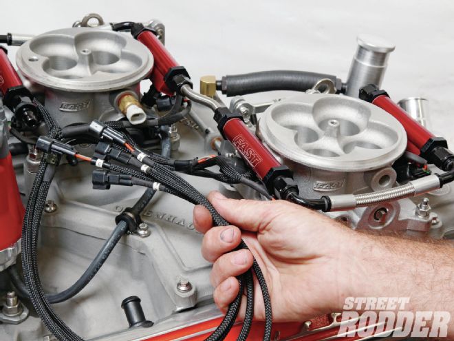 11. McMillan Speed & Fab also created a dual-quad wiring harness specific for the length and shape of this manifold by lengthening the wiring to help clean up the installation.
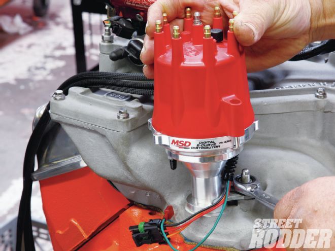 12. We used an MSD E-Curve distributor, which simplifies the installation because it does not require a separate amplifier box and offers a clean, square-wave tach signal (green wire) essential for EZ-EFI. Total timing, vacuum advance, and rev limit are all adjustable using three pots located on the main board in the distributor. With the E-Curve there are no more advance weights to stick, and no more springs to break or stretch.
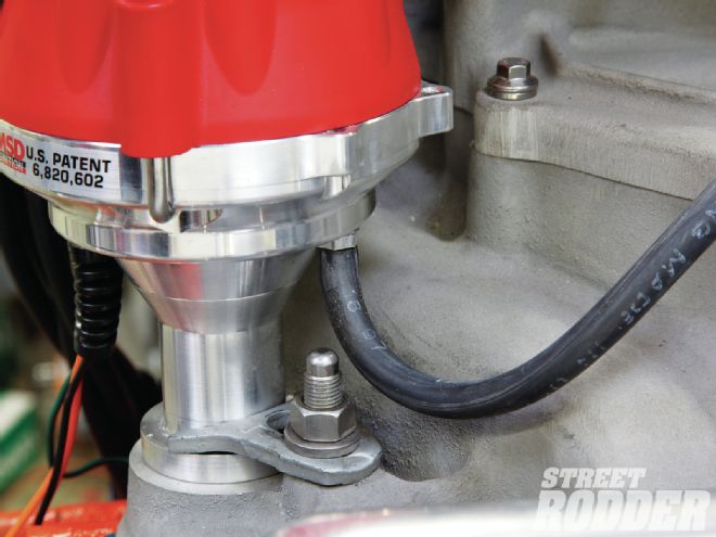 13. The E-Curve distributor uses an on-board MAP sensor for vacuum advance. All you have to do is run this hose to one of the ported vacuum connections on one of the throttle bodies. The great thing here is very accurate vacuum advance and no diaphragm to rupture.
 14. The cast PML valve covers offer a vapor separator that cuts down on pulling oil into the engine. If you want to enhance its performance, you can stuff some coarse steel wool inside the casting to improve its performance.
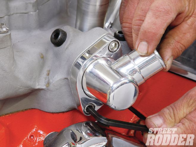 15. To finish off the manifold, we installed a Billet Specialties thermostat housing to add a little bling and a lot of adjustability.
 16. We used stainless ARP fasteners throughout the installation to give the manifold a little extra visual kick. Stainless will also make the corrosion factor almost non-existent.
 17. If you’ve ever driven a street car with open breathers, then you’re familiar with that constant oil smell when using open breathers. That’s why we installed a positive crankcase ventilation (PCV) valve from an ’80s Nissan Maxima only because it offered a 1/4-inch male thread fitting that screwed into our brass manifold adapter.
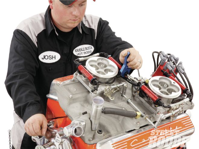
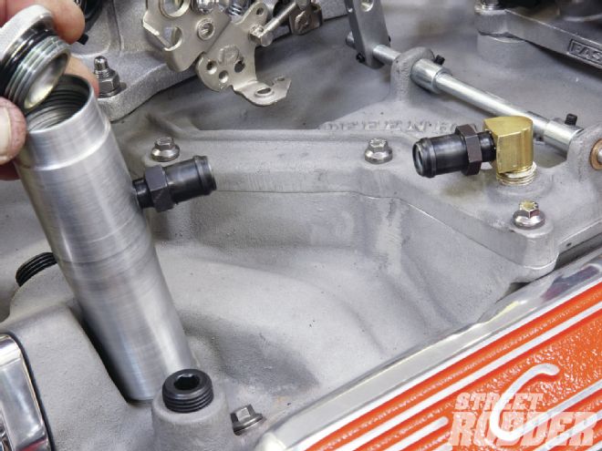 18. We gutted a second Nissan PCV valve and installed it in a custom billet aluminum stand pipe machined by the Josh and the boys at Knuckle Busta Hot Rods in Oxnard, CA. Note the weld on the threaded top from Billet Specialties is sealed with an O-ring to prevent leakage.
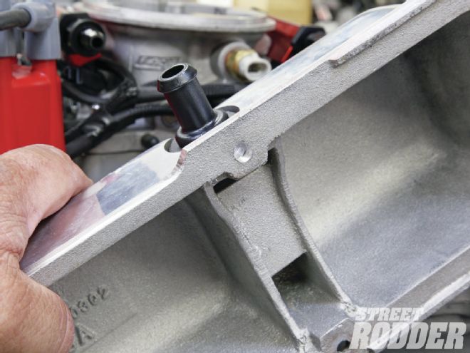 19. Because the cross ram was originally designed for thin, stamped steel valve covers, we had to trim a portion of the valve cover rail to clear the manifold. A couple areas on the manifold also had to be trimmed for clearance.
Oval Antics
Since we were building a manifold similar to a small-block Trans-Am 302 cross ram, we decided to take a cue from the factory with a custom air cleaner instead of a pair of simple 6-inch air filters. The factory used an oval air cleaner assembly to cover both carburetors that looks retro, so we took that idea one step further with a custom billet lid with fins to match the PML valve covers. We started with a 21x10-inch template that we took to our pals at CAD/CAM Consulting in Newbury Park, California. Pete Jorgensen used a picture of the original GM filter assembly to create this slick, finned version of a Trans-Am air cleaner assembly. We are still working on some of the cool design factors so you will only get several small glimpses of it now. Make sure to tune in when we unveil our Retro-Tech 327 in an upcoming issue, you won't be disappointed.
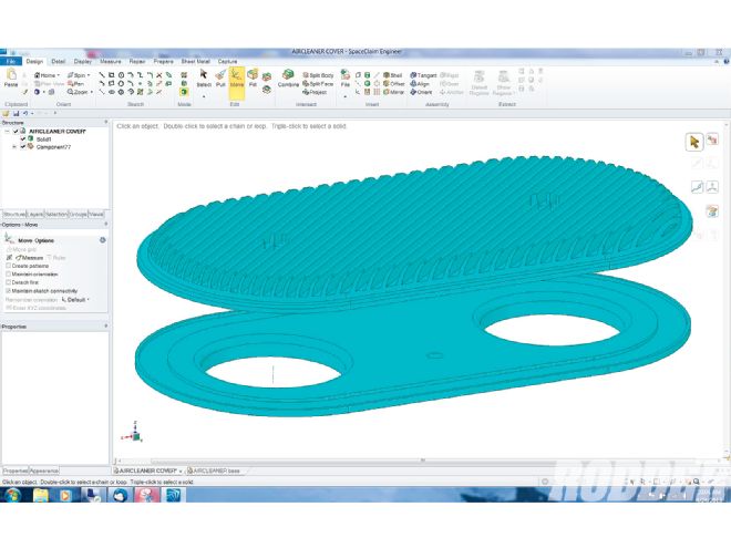 Two different software programs were used to create this awesome piece. The first was a 3-D modeling program called SpaceClaim, which allowed us to see the part long before we made one chip. The second program used was MasterCam, a machining program that makes this job look way too easy. Pictured here is the SpaceClaim program displaying both parts at once.
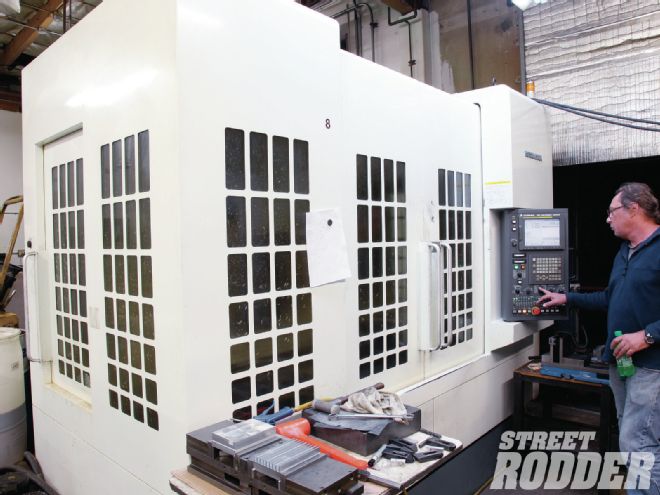 The other thing that made this process easy is having friends with $250,000 Kitamura machining centers that are usually tied up making high-tech parts for the government. A special thanks to Pete, Tom, and Kevin for bringing our dream to life.
 Pete started with a chunk of 24x12-inch aluminum 1-1/4 inches thick to create this result. We actually cut both parts out of the same piece of metal, lots of chips.
Filter Building
A custom air cleaner housing isn't much good without a matching air filter. While we could have built the filter around an existing filter element, that takes all the fun out of having a custom filter. What we discovered is that K&N will build a custom air filter element for anyone if you have filter dimensions for your application. We followed along as K&N built two filter assemblies for our EZ-EFI–equipped cross ram.
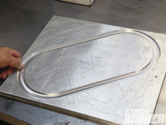
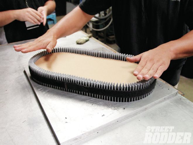
1. We supplied the tooling for the air filter by milling a 1-inch wide by 1/4-inch deep oval in a large piece of aluminum plate.
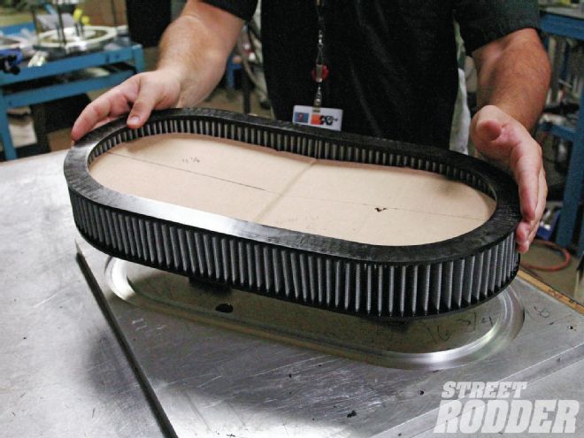
 2. K&N created a 21x10x3-inch filter from base stock that they crimped together to create an oval.
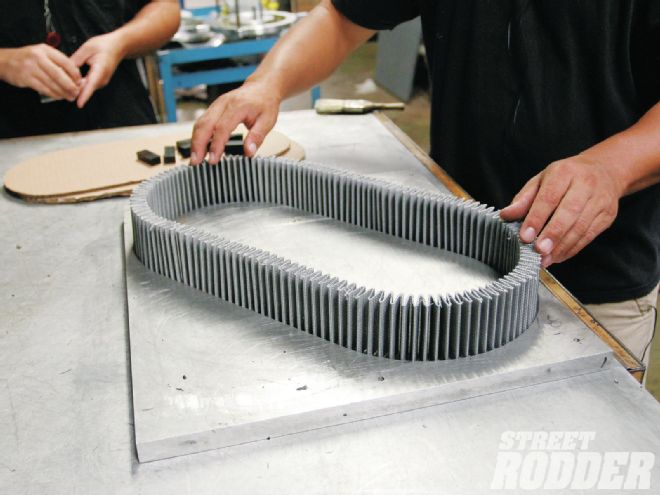 3. The technician placed the filter in the milled tooling plate and checked for proper fit.
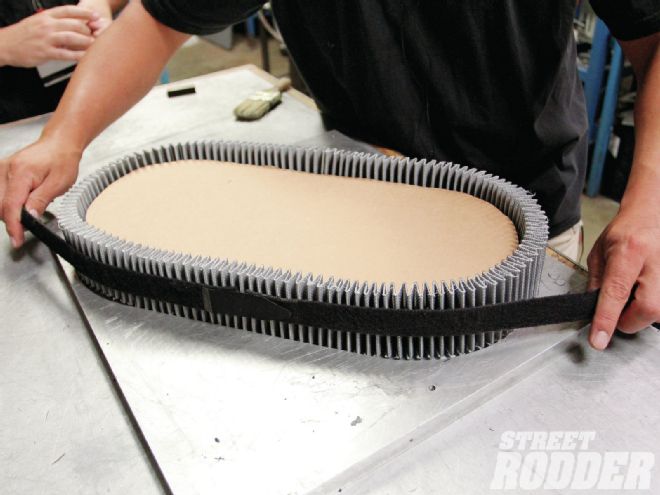
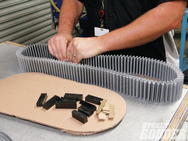
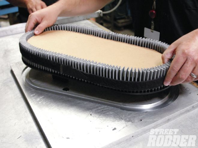
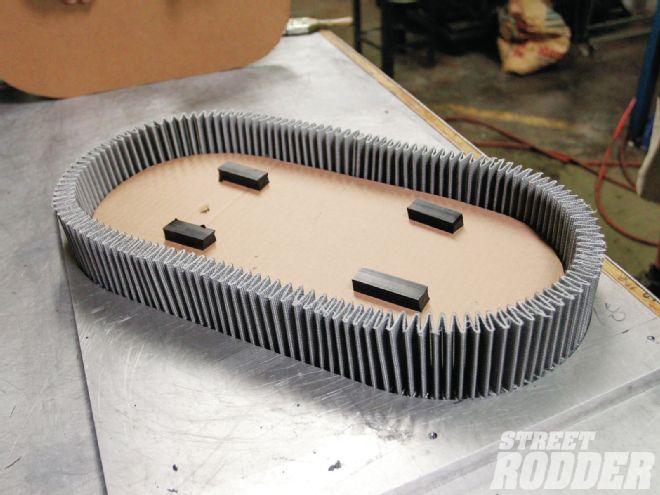 4. Four rubber blocks were used underneath a layer of cardboard followed by a second layer of spacers and cardboard to maintain the filter to its proper shape while being made.
5. An elastic band is used to maintain the filter’s shape during the casting process.
4. Four rubber blocks were used underneath a layer of cardboard followed by a second layer of spacers and cardboard to maintain the filter to its proper shape while being made.
5. An elastic band is used to maintain the filter’s shape during the casting process.
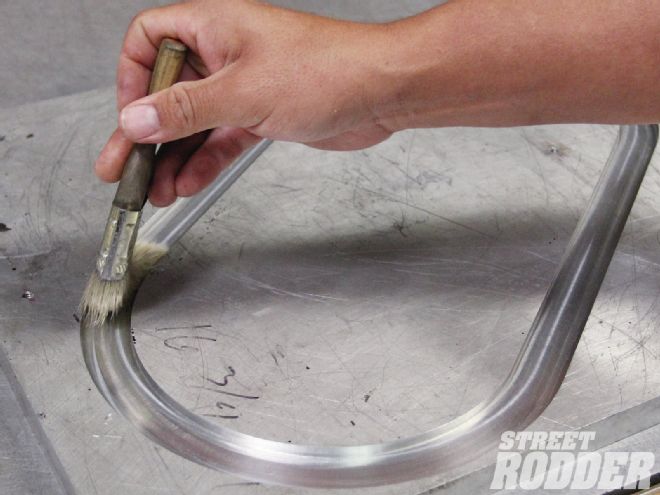 6. Mold release is applied to the tool to prevent damage to the rubber once it’s dry and to make it easy when removing the part from the mold.
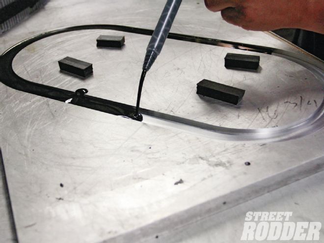 7. Pouring the urethane rubber material into the mold slow and easy ensures that you achieve the proper thickness top and bottom on the finished filter.
 8. The filter is set in the urethane mold and held in place with a weight until it has taken a set. The urethane dries in 15-20 minutes, which makes the process very quick.
 9. The mold release did its job and made it easy to remove the first step from the tool.
10. The K&N technician repeated the step for the top portion of the filter, and with that, we have a custom-built filter.
9. The mold release did its job and made it easy to remove the first step from the tool.
10. The K&N technician repeated the step for the top portion of the filter, and with that, we have a custom-built filter.
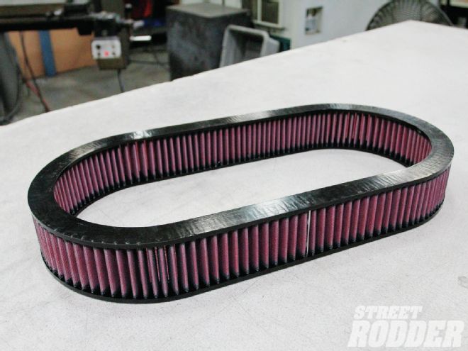 11. Here’s the final filter, oiled and ready to be installed in our cross-ram manifold.