Week after week you sweat the details, getting your car race ready. When it comes to your race program, there's nothing more important than the details of your engine. If you are like many racers, building an engine is a do-it-yourself part of your racing program, and you're always looking for ways to maximize engine performance.
Circle Track thought it would be helpful to take a look at some of the things that can be useful in improving engine performance. What we came up with is that much of your engine's potential lies in making sure that you have the valvetrain geometry right. By understanding and applying basic valvetrain geometry theory to an engine program, you will be on the road to claiming the maximum power your engine can deliver. So, we decided that this story should accomplish three things: 1) Seek out basic valvetrain theory. 2) Understand what valvetrain theory should look like. 3) Do a valvetrain setup and apply what we learned.
In seeking some understanding about valvetrain theory, we spoke with noted engine research specialist, Jim McFarland of AutoCom Incorporated in Austin, Texas. According to McFarland, valvetrain theory, once understood, can serve as a universal template for acquiring the most performance from your engine, no matter what kind of racing you do.
Fundamental to this theory is an understanding that the camshaft is attempting to deliver its motion message to the intake and exhaust valves. This cam message ultimately dictates cylinder pressure. The resulting pressure, along with the fuel burn in the combustion chamber, is transmitted by the piston to the crankshaft as torque.
There is a measurement used in calculating how well the cam message is being delivered to the valves, and the measurement is called Indicated Mean Effective Pressure or IMEP.
Mathematically, IMEP is derived from the difference between negative torque (the pressure on the crank working against the piston coming up to TDC on the compression stroke) and positive torque (the pressure on the crank working with the piston going down after TDC on the power stroke). The arithmetic difference of these figures is called IMEP, and this measurement is what the crankshaft sees.
Because maximum torque is the performance needed from your engine, it's necessary to understand that IMEP can be affected, positively or negatively, by valve opening and closing. So it follows: If you maximized all the motion the camshaft is designed to deliver, as far as intake and exhaust valve actuation is concerned, you have minimized the losses you get to IMEP.
According to McFarland, IMEP is a quantity physically determined by either measurement within the combustion space of a running engine, using the techniques of engine-cycle analysis or calculated using certain data as typically measured in a laboratory environment. As a tool, IMEP can tell you much. However, it's less important that you know the actual measurement and much more important that you understand what it takes to create IMEP. It's also important to know that there are things within your control that can positively influence this quantity, and anything you can do to positively influence IMEP translates into higher performance from your engine.
When it comes to the valvetrain geometry influences, the variable players are pushrods, rockers, and valves. Each is critical in delivering the cam message, so it becomes obvious that correct geometry of these parts has a direct influence on maximizing IMEP.
D facility of Competition Cams in Memphis, Tennessee. Our goal here was to learn what correct geometry should look like, and Griffin explained that it could be illustrated in a diagrammatic way.
The diagram shows the preferred roller-to-valve contact during its valve motion cycle (Figure 1). As illustrated here, at mid-valve lift, a 90-degree angle is formed between the valve axis and points formed by the centerline of the trunnion and the vertical centerline of the roller tip. This geometry is preferred because it does two positive things concerning valvetrain motion transfer. First, it's the best configuration to deliver the specific cam message to the valve. Second, this geometry causes the roller tip to stay more centralized during its cycle, thus eliminating side loading of the valve. As a graphic depiction of valvetrain geometry, the diagram represents a theoretical best-case scenario. Although compromises to this are common, the closer you come to achieving this angle the more likely you will experience the best performance from your valvetrain and maximize IMEP.
Before moving to our goal of assembling a valvetrain, we thought this was a good place to stop and get some suggestions on checking out the parts before an installation begins. We talked with engine specialist Larry Radnick of Darrell Waltrip Motorsports in Harrisburg, North Carolina, and asked for any tips on checking out the parts before you start.
Radnick said there are a number of things to check before you assemble the valvetrain. Much of it is common sense, but it's important since small problems now can add up to denigration of the cam message and losses to IMEP later. Pushrods should be straight, so check each one. There are a number of gauges or tools to accomplish this, however, the simplest way is to roll them across a flat surface to check for wobble. Pushrods that aren't straight should be replaced.
Whether you're using roller rockers or stock rockers, check the rockers to make sure you have the ratio you intend to use. Inspect the surfaces for any defects. Look at the pushrod seat for security and the rollers for freedom of movement. Make sure to check that you have all the hardware for installation. Valves should be thoroughly checked for surface defects and proper seating characteristics. Defective valve-stem surfaces can cause scrubbing, and any surface defects should be polished out. Improper seating characteristics can obviously create cylinder pressure problems.
For a valvetrain assembly walk-through, we went to see engine specialist Keith Dorton of Automotive Specialists in Concord, North Carolina. Our goal here was to put theory into practical application with emphasis on maximizing the valve motion and minimizing the losses to IMEP. Dorton was in the process of assembling a Chevrolet Sportsman motor. The motor utilized a stud-mounted rocker system, so we asked to be taken through a step-by-step process of achieving correct valvetrain geometry.
The cylinder head had been prepared and was ready for pushrod and rocker installation. Dorton took a moment to note the importance of making sure stud mounts were aligned properly (Photo 1). Most stud-mounted rocker systems allow for some alignment flexibility, so that the rocker roller will contact the valve tip properly. It's important to check this carefully since misalignment will cause undesired valve motion and geometry (Photo 2).
The first step in the assembly process was to color the valve-stem tip with a black marker (Photo 3). Next, a pushrod and rocker were put into place, and the rocker was tightened enough to remove the lash (a 7.800-inch pushrod was used) (Photo 4).
The motor was then rotated to allow the valvetrain to go through a couple of complete motion cycles (Photo 5, Lead). With this accomplished, the rocker was removed and a pattern revealed on the valve-stem tip. In this example, the pattern was unacceptable because it was off center and suggested the pushrod was too long (Photo 6). This configuration creates a rocker-to-valve motion that causes valve-side loading and short life of the valve guides. Both of these factors will lead to losses to IMEP and premature engine part failure.
The valve stem was marked again, and the procedure was repeated using a 7.750-inch pushrod. This time an optimum rocker-to-valve pattern was revealed. In this example, the pattern was central to the valve stem and suggested the pushrod length was correct (Photo 7). Valvetrain geometry that yields this pattern is preferred, producing correct valvetrain geometry and optimum valvetrain motion.
D shaft system. Correct installation of shaft-mounted systems rests on having the bar height set correctly.
D system, if the gauge does not fit flat across the valve-stem tip, different thickness shims are required. During this procedure, Dorton explained that sometimes due to work done on the cylinder head and manufacturing variables, shaft-mounted systems occasionally don't produce an exact fit. On such occasions, finding a happy medium is the solution. In this example, the bar height was correct on the first try (Photo 8). Once the proper bar height is found, correct valvetrain geometry can be obtained by using the same process employed in the shaft-mounted system.
While we were on the subject of shaft-mounted rockers, Dorton showed us a trick he uses in checking the geometry, after the motor is completely assembled. In this example, the valve was being held in place with a checking spring and the retainer installed. The geometry of the shaft-mounted system was checked using a modified gauge that cleared the retainer (Photo 9). This allowed the geometry to be verified on a fully assembled cylinder head. Dorton explained this method can be useful as a general check of the shaft-mounted rocker geometry before and after running the motor.
As this entire exercise shows, achieving correct valvetrain geometry rests largely on determining the correct pushrod length in any given application. According to Dorton, inaccurate pushrod length is a common cause for failure in achieving correct valvetrain geometry. By applying this basic installation process, you can achieve the best valve motion and improve your engine's life as well as its performance.
For one more word on the subject of correct valvetrain geometry, we visited Dingler Racing Engines in Cumming, Georgia. As a 30-year veteran of race engine building, we asked Gary Dingler to walk us through a valvetrain setup using stock-type rockers. As before, the head had been prepared and was ready for pushrod and rocker positioning. The installation process began by marking the valve-stem tip with a black marker. Instead of a standard pushrod, a variable pushrod-checking tool adjusted to measure 7.800-inch was inserted, and the rocker was tightened into place (Photo 10).
Before turning the motor through its motion cycle, Dingler pointed out that when establishing correct pushrod length on a stock-type rocker system, it's important to observe the rocker for clearance to the stud. Failure to maintain the proper clearance will cause pushrod or stud breakage and engine failure. After turning the motor a couple of revolutions, the rocker was removed to look at the resulting valve-tip pattern (Photo 11). The pattern indicated improper geometry due to an incorrect pushrod length. Once again, this kind of configuration creates valve-side loading which leads to losses to IMEP and premature engine part failure.
The process was repeated using a 7.700-inch measurement on the adjustable pushrod tool. With the valvetrain rotation concluded, the rocker was removed and the pattern was revealed (Photo 12). This time, the preferred pattern was realized. Once again, this pattern is preferred since it produces correct valvetrain geometry and thereby promotes peak IMEP.
In the end, it's clear that sweating the details is a formula for success.
Through diagrammatic representation and practical application of theory, we've seen that power gains can be discovered by achieving correct valvetrain geometry. It's also clear that when it comes to racing engines, these fundamentals apply to any engine type.
Now that you have a template of theory and application to use in your engine program, you can increase the possibility for greater performance from your engine. The good news is: You have control.
Proper stud alignment is an important part of correctly installing a stud-mounted system. Correct alignment is one of several components used in achieving correct valvetrain geometry.
To illustrate proper stud alignment, a Crane stud-mounted rocker system was used. Correct stud alignment causes the roller tip to fit squarely on the valve tip. Once the rocker is installed, this is the preferred roller-to-valve location.
With the studs mounted and the valvesprings installed, the valve tip is colored with a black marker in preparation for checking for correct geometric pushrod and rocker fit.
At this point in the process, the rocker is put into place and tightened enough to remove the lash.
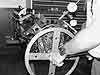
With everything assembled, the motor is rotated allowing the valvetrain to go through a complete motion cycle.
With the motor revolutions completed, the rocker is removed and the roller-to-valve pattern is revealed. This first example revealed an unfavorable pattern that was off center, indicating an incorrect pushrod length. This geometric configuration will cause valve-side loading, which will lead to lowered engine performance and engine part failure.
Repeating the process using a .050-inch shorter pushrod produced this pattern. This configuration is more central on the valve tip, and is the preferred roller-to-valve geometry. Achieving this pattern assures correct pushrod length and promotes reduction of any valve-side loading.
D system is checked with the manufacturer's supplied gauge. With the shaft bolted in place and the valve in the fully seated position, placing the gauge across the bar to the valve stem checks the height. Bar height is correct when the gauge rests squarely across the bar and over the valve-stem tip.
This modified checking gauge is useful in a general check of geometry accuracy before and after running an engine.
Setting geometry on this stock rocker system is accomplished using an adjustable pushrod tool to obtain correct pushrod length.
In this example, the pushrod tool was set at a length of 7.800 inches. The pattern is well off the valve-stem tip center of the valve tip and indicates improper geometry due to an incorrect pushrod length.
This example produced the preferred center pattern on the valve tip. This geometry is correct and was achieved by shortening the adjustable pushrod tool to a length of 7.700 inches.