Back in the November 2013 issue of CUSTOM CLASSIC TRUCKS we showed how our own Jason Scudellari went about modifying the firewall and mounting Wilwood swing pedals in his 1956 Chevy pickup. As we explained then, Jason plans on taking his truck to track events so the engine has been set back in the chassis 6 inches to put more weight on the rear wheels.
Moving the engine to the rear is one of those good news/bad news scenarios. The good news is sliding the engine to the rear will no doubt improve handling, the bad news is the engine now intrudes further into the passenger compartment and that complicates a few things. So far the firewall has been fixed. This time around Jason builds a new transmission tunnel and installs the steering column.
To put the steering wheel at a comfortable angle for tossing the truck from one heading to another, Jason chose a Flaming River 30-inch-long tilt steering column without an ignition switch (part number FR2000FB). The U-joints and steering shaft needed to get past the Doug's headers, as well as the steering wheel and column drop, also came from Flaming River.
One of the other ramifications of moving the engine is that the transmission goes with it—and that meant the transmission tunnel had to be revamped. To simplify that chore Jason got in touch with Engineering and Manufacturing Services, or EMS for short, and ordered a pair of universal transmission tunnels (part number 804 for the larger version and 808 for the smaller). Both are die stamped in the USA from 18-gauge steel.
With all the parts on hand and with a rare lull in activity in the Source Interlink Tech Center, Jason Scudellari took the rare opportunity to focus on his project. Here's what our resident Tech Center manager was up to when no one else was around.
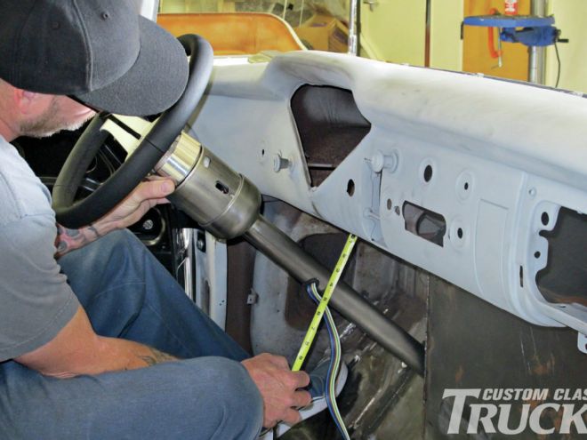
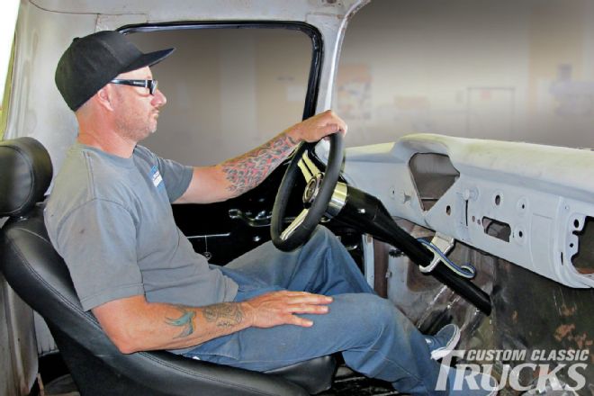 1. Jason Scudellari checked the location of the Flaming River steering column and wheel to ensure it was in the right position for looking cool while cruising or attacking an autocross course. At one point during the process CCT Editor Ryan Manson swears he heard engine sounds coming from the cab.
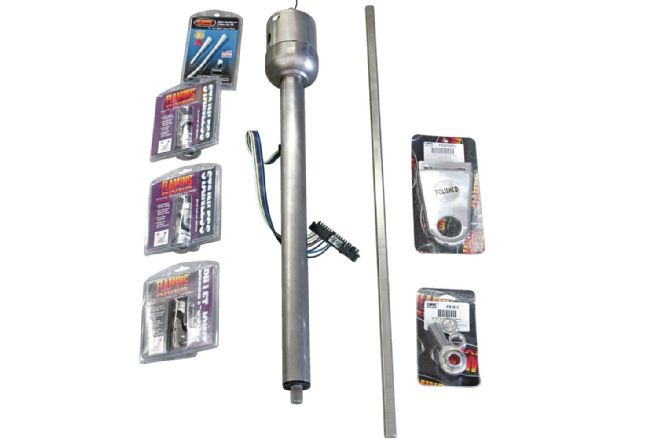 2. Flaming River supplied the full complement of components to make the column easy to install and safe in operation.
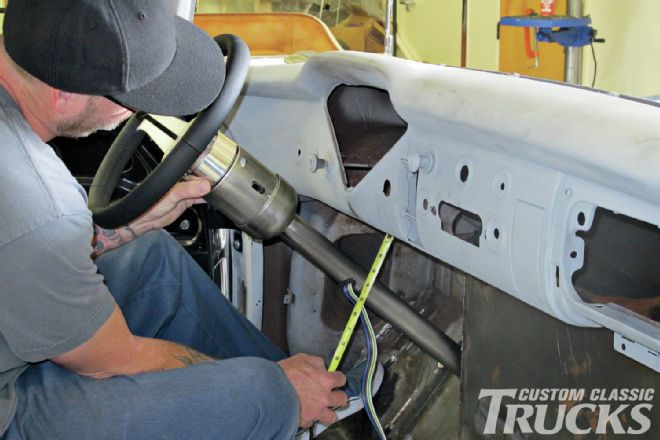 3. With the steering wheel and column mocked up, Jason measured for the dash mount.
 4. Flaming River’s swinging column mount is made in two pieces—the upper portion attaches to the dashboard lip, the lower portion can rotate to accommodate the angle of the steering column.
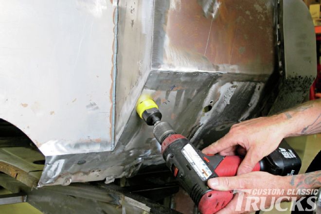 5. Jason used a hole saw to cut an opening for the steering column in the recently remodeled toeboard.
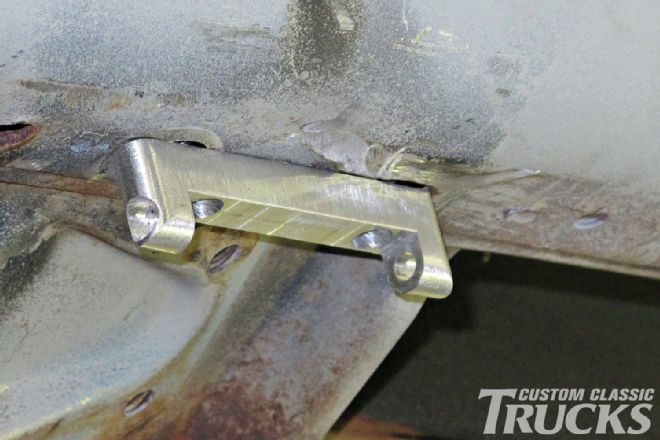
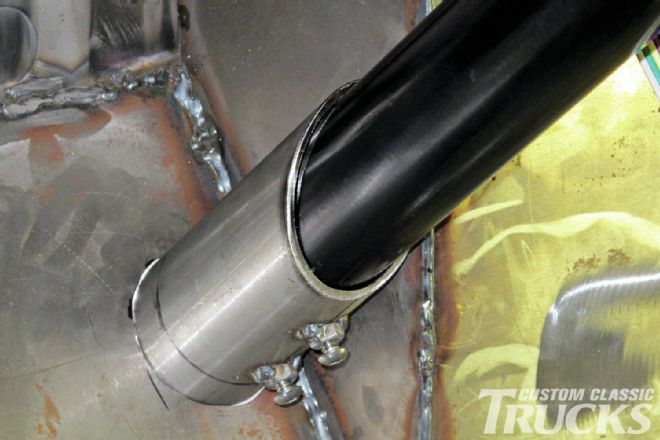
 6. A lower column mount was fabricated from a length of tubing. The holes are for screws that will secure the column.
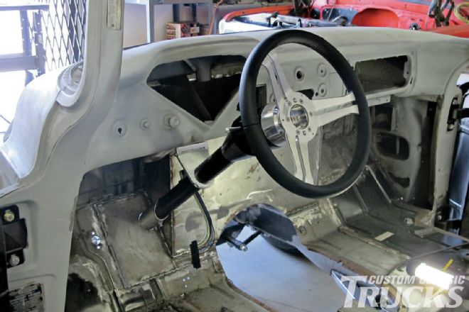 7. To double-check the angle of the column, a test fit was made. Note the swinging dash mount and the black Flaming River Navigator leather-wrapped steering wheel (part number FR20164BK) that mounts with an adapter (part number FR20119BA).
 8. Securing the column to the lower mount are two screws with nuts tack welded to the tube.
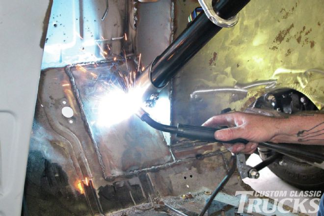 9. With the proper positioning of the lower mount confirmed it was welded to the floor.
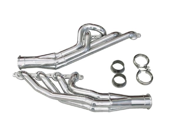 10. The LS1 powering the 1956 will exhale through a set of ceramic-coated headers from Doug’s.
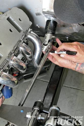 11. With a Flaming River 1x¾-inch double D stainless steel U-joint (part number FR2517DD) attached to the steering column, a ¾x36-inch stainless double D shaft (part number FR1851SS) was marked to be cut.
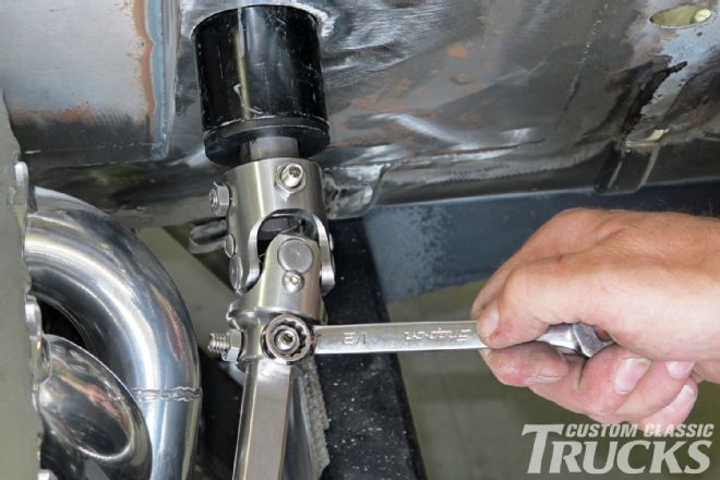 12. The shortened shaft was dimpled with a drill bit then the setscrews were installed and secured with the included lock nuts. At the bottom of the shaft another U-joint attaches to the Flaming River rack-and-pinion steering.
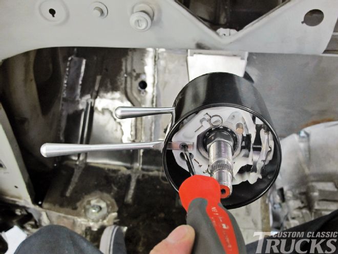 13. Before installing the steering wheel, the smooth billet turn signal and tilt levers were installed.
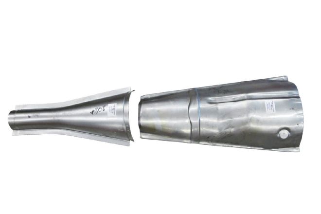 14. Along with precision-fit patch panels for a variety of cars and trucks, EMS offers these universal transmission covers—(part number 808 is on the left, 804 on the right).
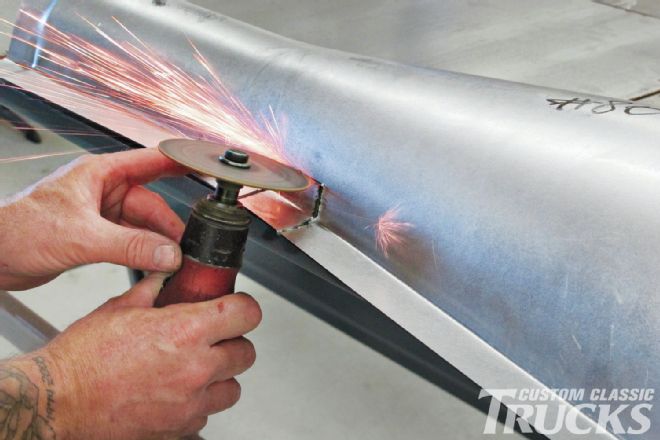 15. To keep the tunnel as small as possible, Jason elected to use the smaller 808 version. Here he cuts notches to clear the floor’s reinforcements.
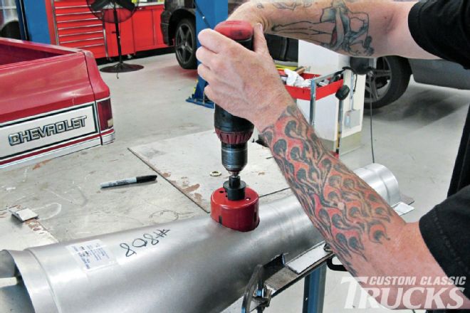 16. With the tunnel clamped to the workbench, and after careful measuring, a hole was cut for the shifter.
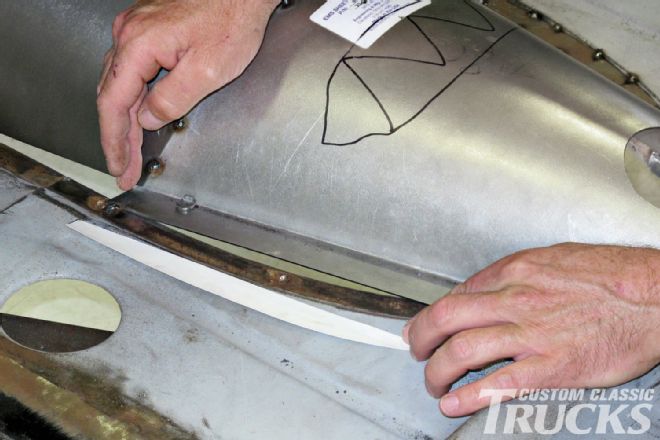
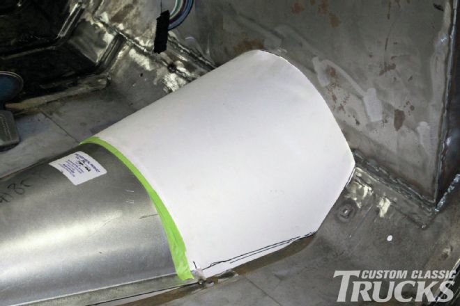 17. A paper pattern was made for the filler panel necessary to fill the gap between the EMS tunnel and the firewall.
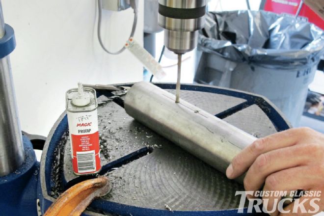
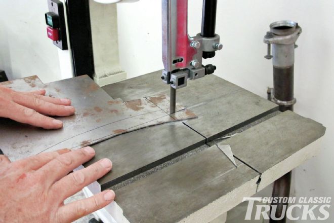
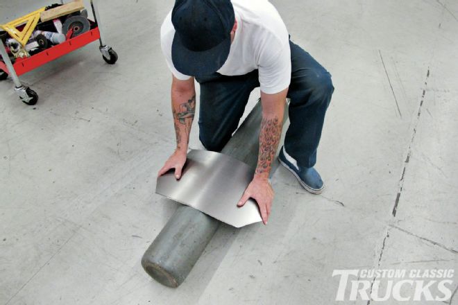 18. With the pattern transferred to sheetmetal, the time-honored trick of forming a curve over a welding cylinder was used to get the desired shape.
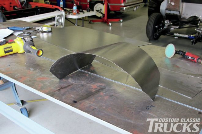 19. After a trial fit or two and some careful bending, the filler panel looked like this—it fit perfectly.
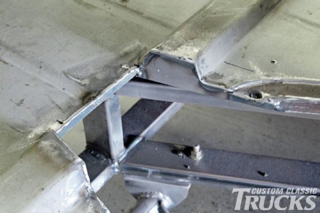 20. To provide transmission clearance, the floor brace had a section removed and the ends boxed.
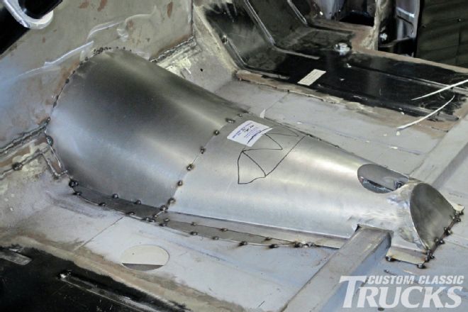
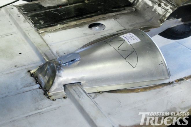 21. The rear portion of the EMS tunnel was shortened and capped, then tack welded in place.
 22. With the filler panel in place it was tacked to the firewall.
 23. Inside the two tunnel pieces were tacked together. The front portion will require an added flange to attach to the floor.
 24. Two smaller filler strips would also be added to the EMS tunnel to close the gap in the floor.
 25. All the necessary strips to fill the gaps between the tunnel and floor were cut from 18-gauge sheetmetal.
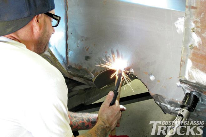
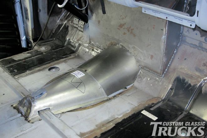
 26. With the filler pieces in place, more tack welds were added to all the joints. In some cases a removable tunnel provides transmission access—in this case the transmission is easily serviced or removed from below.
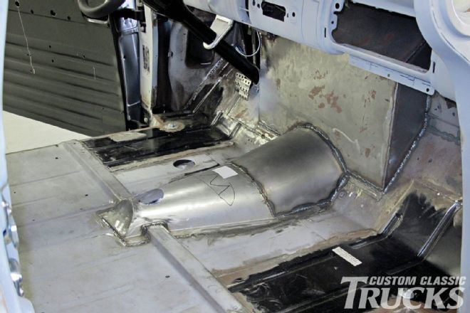 27. A little more time with the MIG welder and the floor was permanently secured. Given the engine setback, the tunnel’s intrusion into the interior is minimal.