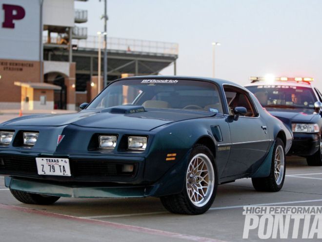
In last month's issue, we introduced the '79 Trans Am that was the subject of our suspension upgrades and the parts included in the build. This month, we wrap up the installation and compare the results of before and after testing.
Our partner in this build was Pro-Touring F-Body (PTFB). "Whether your Second- Gen is a driver or destined to compete in a myriad of road racing venues, our line of suspension kits and chassis components can assist," says PTFB's owner Dave Masello. "PTFB was born from my obsession to make my Second-Gen Trans Am handle on par with the best Pro-Touring setups on the market, but at a budget price. The ability to engineer parts that raise the bar for the platform and still provide individual customer service sets us apart."
Hang on as we finish up the installation and test the combination. Will the Bandit-era Trans Am eat up the road without eating up our project budget? Read on and let's find out.
The results
For a conservative investment in the suspension and the right combination of wheels and tires, the Second-Generation Trans Am can easily surpass the best stock Fourth-Generation Trans Am and push upwards of 0.90 g's.
During baseline testing, it became painfully obvious to us that the Trans Am's BF Goodrich Radial T/A tires on 15x8-inch factory wheels were very close to being maxed out on lateral grip. Swapping the wheels to 17-inch replacements and wrapping them in BFGoodrich Comp-2 tires increased the lateral g's by 0.06.
The biggest handling deficiency turned out to be the original body and core-support bushings. According to Dave: "Enthusiasts usually overlook a suspension in their quest for performance, but much like the results with the smaller wheels and tires, increasing power without the hardware to turn it into forward motion is not dollars well spent. For the vast majority of enthusiasts, simply changing to a solid body bushing will not result in a stiff, jarring ride if done in conjunction with our subframe connectors. Build a solid foundation and then put the power to it."
Although higher average g's would have looked better, our testing did not have the luxury of a professionally groomed race track. After seeing results lower than expected, we brought out a new Cadillac CTS-V to establish an objective baseline, and it averaged 0.79 lateral g's. (Motor Trend recorded a 0.91 g average with the same car.) Knowing that we were up against test-surface deficiencies, we focused on measureable gains, not the overall g's. The gains from the larger tire section width and stiffer sidewall were well noted in the baseline test (from 0.76 to 0.82), but an additional 0.05 g's were attributable to the suspension changes.
When all was said and done, the Trans Am not only looked the part of a well-handling street machine, but turned in numbers that bested stock Fourth-Gen WS6 handling results. The investment in the suspension increases the owner's driving experience and sets the foundation to effectively use future power increases.
Ride Height Before and After Ride Height (in inches) Stock PTFB Front Left 25.25 24.875 Front Right 25.25 25.25 Rear Left 25.25 25.25 Rear Right 25.00 25.50 Note: All measurements were made from the bottom edge of the wheel to the bottom edge of the fender. The new Pro-Touring F-Body suspension could potentially settle more.
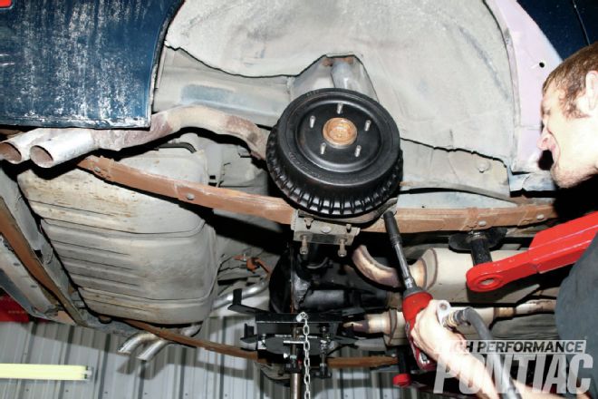
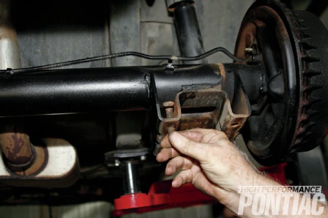
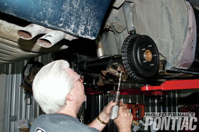
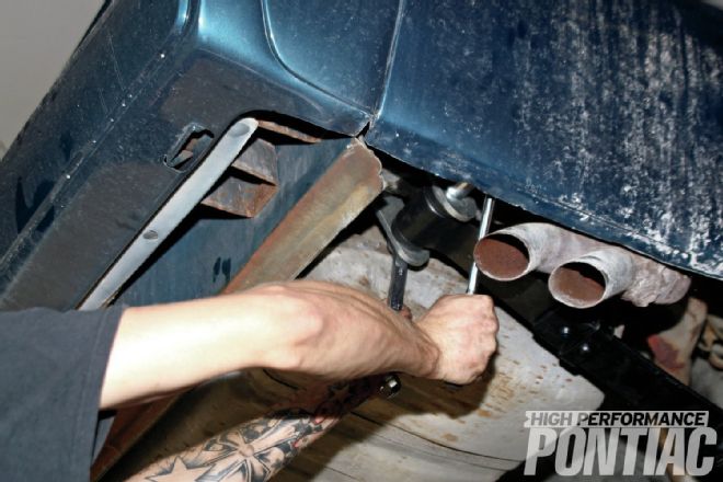
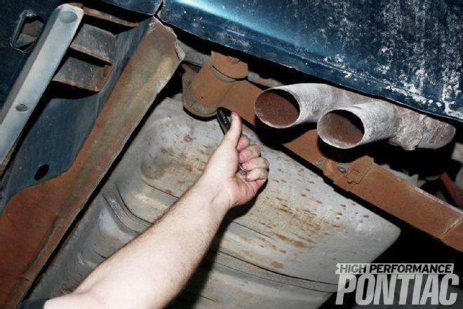 1. After supporting the rear end with a transmission jack, the rear-spring hardware was sprayed with penetrating oil and the top and bottom shackle nuts were loosened with an 11⁄16-inch wrench.
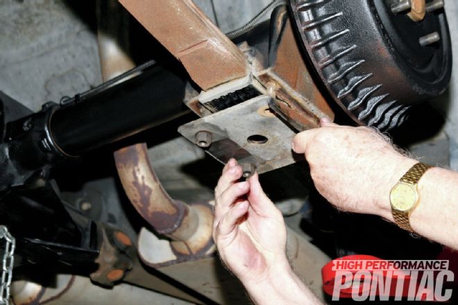 2. The center support for the leaf spring is a bracket welded onto each side of the axle with the leaf spring sandwiched between the upper and lower rubber bushings. It’s all held in place by U-bolts, nuts, and a spring and shock-absorber anchor plate.
 3. The 11⁄16-inch plate bolts were loosened, along with the parking-brake cable and retainer (which is unbolted and placed to the side) allowing the plate and upper and lower rubber insulators to be removed. Note how nice a job the Mar-Hyde One Step Rust Converter works to spiff up the brake drums and rear end.
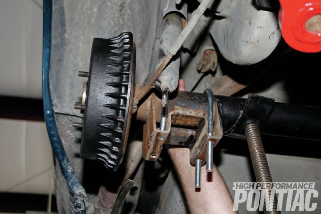
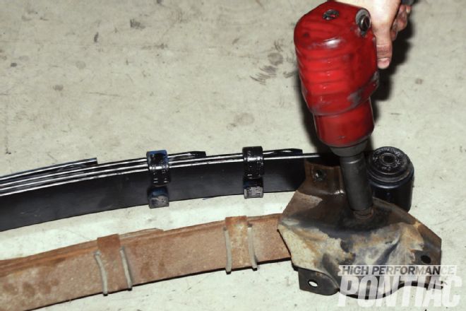 4. The front leaf mount was removed with a 3⁄4-inch wrench, and the nut and bolt that hold the rear of the leaf on the shackle was removed, allowing the leaf spring to come free. The leaf mount (front hanger bracket) was then taken off the spring.
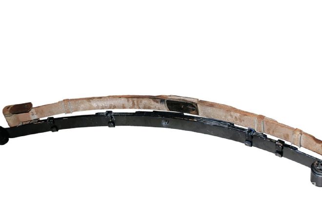 5. Side by side, the Pro-Touring F-Body leaf spring measures 50.2 inches versus the stocker’s 42.7 inches. Both assemblies have the same number of leafs. According to Dave: “The PTFB leafs are engineered for a more performance-oriented ride and utilize longer front leafs to reduce wheelhop.” The difference in overall length is indicative of stock leaf-spring sag and the engineering used by PTFB to achieve a stock ride height.
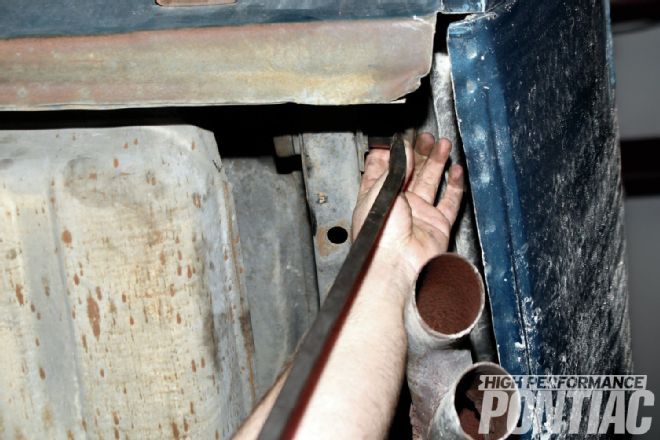 6. A prybar and plenty of patience were used to remove the subframe bushings for the leaf-spring shackle mounts.
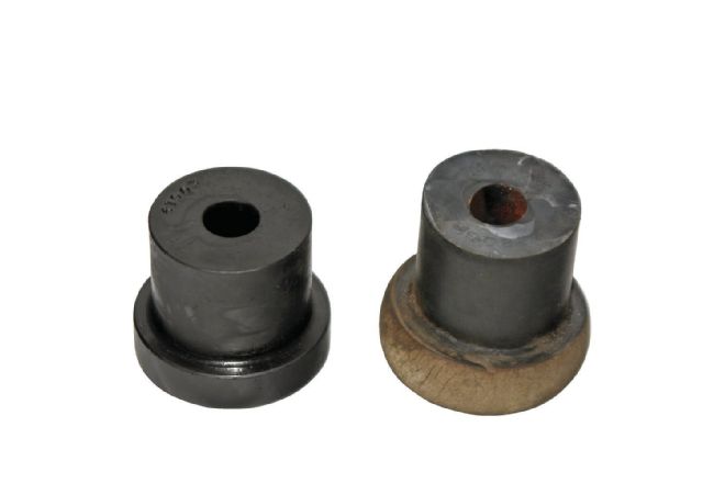 7. Once removed, a comparison of the stock bushing on the right and the PTFB bushing on the left illustrates how the stock rubber bushings crack and deform with age. PTFB’s proprietary polyurethane bushings are engineered to last a lifetime, and significantly reduce spring deflection and bushing deformation.
 8 Pre-installation of the bushings began with putting them in the freezer for a two-hour nap, then applying liberal amounts of silicone grease to them. Installation was done with a prybar.
 9. PTFB offers polyurethane bushings on the rear-leaf spring end but a true spherical bushing, called a Sphere-O-Bushing, on the front-leaf eye. We opted for the former bushing on the front eye, and all four bushings were frozen before being installed with a rubber mallet. Note the new rear-shackle hardware being readied for installation.
 10. The factory axle bracket for the leaf springs used captured bolts and nuts on the inside rather than U-bolts that went over the axle (like the outside which was removed). PTFB supplied beefy new 1⁄2-inch U-bolts and nuts with its kit.
 11. The 1⁄2-inch U-bolts are significantly stronger due to the increase in steel thickness, but require that all four bracket holes be drilled out to 1⁄2-inch to accommodate the larger U-bolt dimensions.
 12. We elongated the bolt holes a tad after drilling the bracket out to avoid having to fight with getting the U-bolts through the plate during the installation process.
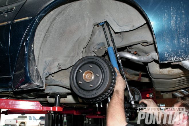 13. Before installing the new leaf-spring assembly, we removed the rear shock-absorber bolts on the top with a 1⁄2-inch socket and extension. After removing the lower attaching bolt, we affixed the new rear PTFB shock absorber and torqued it to spec.
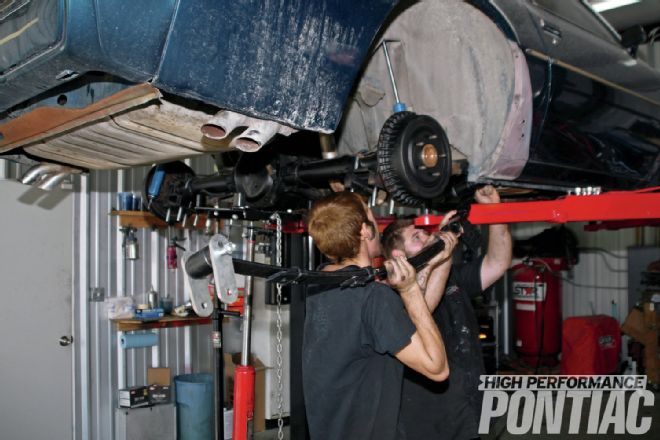 14. We prepared the leaf spring for installation, and then had two able-bodied helpers provide assistance. Whiteside Custom’s Mike White is shown installing the front hanger bracket bolt through the leaf eye.
Stock-Radial T/A Modified-Radial T/A Slalom MPH 55 60 *Lateral g's (avg.) 0.76 0.77 Stock YO/Comp2 Modified YO/Comp2 Slalom MPH 62 65 *Lateral g's (avg.) 0.82 0.87 T/A-Testing Tire Pressure RF/LF Tire Pressure RR/LR Stock Radial TA 38.0/38.0 38.0/38.0 Modified Radial TA 38.0/38.0 38.0/38.0 Stock BFG Comp2 35.5/35.5 35.5/35.5 Modified BFG Comp2 30.5/30.5 34.0/33.5 All pressures noted are optimal pressures achieved during best runs.
Test Parameters
Testing was conducted on a 600-foot slalom course and 200-foot skidpad. Both courses were concrete rather than asphalt, and had incongruities inherent in them that would affect the results compared to dedicated testing facilities run on asphalt that were perfectly flat and concentric. In order to determine if the slalom and skidpad were skewing the results, we utilized a '13 Cadillac CTS-V wagon to benchmark against published tests and then adjusted the skidpad numbers to be reflective of a standard course. No adjustments were made to the slalom numbers.
Benchmarks '13 Cadillac CTS-V Wagon Slalom mph 67 Slalom mph N/A Lateral g's (avg.) 0.79 (unadjusted) Lateral g's (avg.) 0.91 *Adjustment Factor 1.422 '76 Trans Am Slalom mph 54.9 Lateral g's 0.785 '00 Trans Am WS6 Slalom mph 64.6 Lateral g's 0.84
Tools and Supplies Prybar Cut-off wheel Penetrating oil Metric socket set Metric wrenches Torque wrench Drill and drill bits Pole jack Floor jack
Torque Specifications Fastener Torque (ft-lb) Bolt: shock-absorber lower retaining 10 Bolt: shock absorber, upper retaining 20 Bolt: spring and shock absorber anchor plate 40
 15. The rear shackle was then installed on the top bushing and torqued to spec. Next, the lower shackle bolt was installed and tightened with a 7⁄8-inch open-ended wrench and 21mm socket.
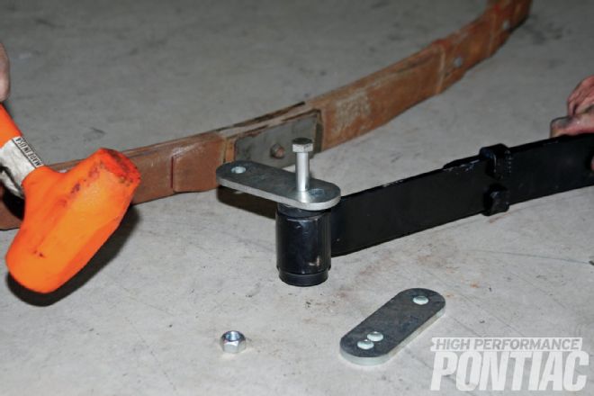
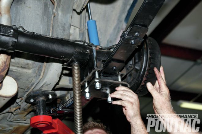 16. All that remained was to affix the center plate. The new PTFB upper and lower Teflon infused isolators are sandwiched in place, and then the plate, U-bolts, and nuts are attached and torqued to spec.
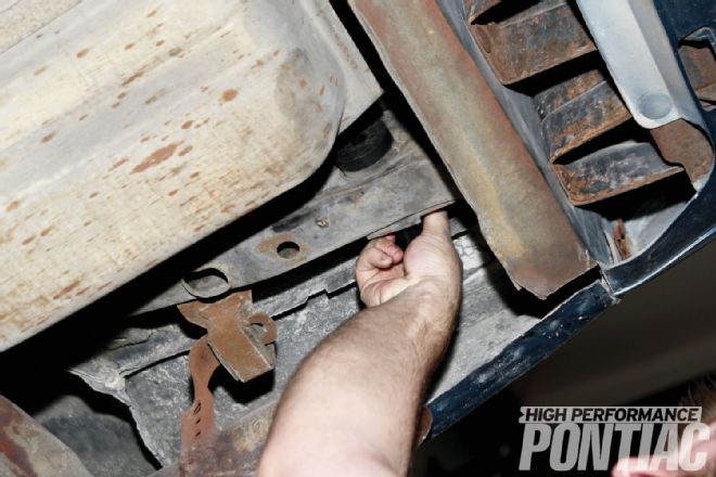
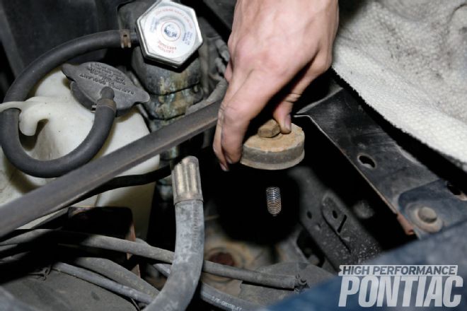
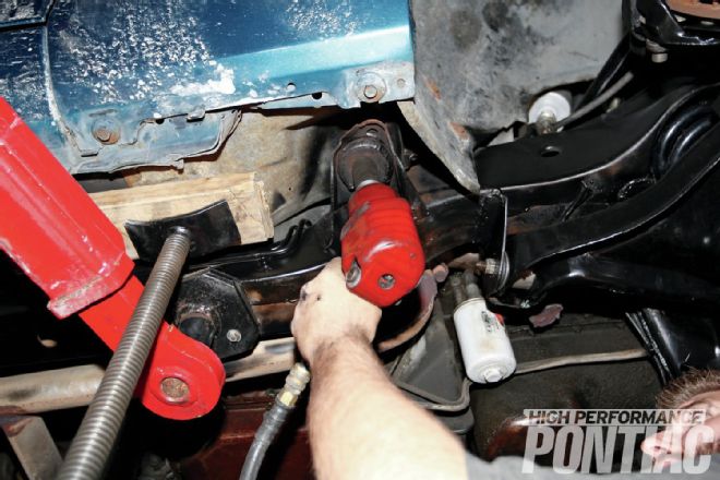 17. After completing both sides of the Trans Am’s leaf springs, it was time to replace the factory body bushings with PTFB’s 3-in-1, Key-Lock Solid Body Bushings. We positioned a pole jack on the passenger side beside both stock body bushings, raised the pole jack to pull the body up from the subframe, and used a 24mm socket to remove the long bolt. We were extremely careful during this procedure as the body was resting on screw jacks.
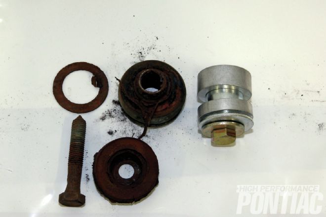 18. We pulled out the bottom bushing and used a screwdriver to remove the top half of the clamshell bushing. The stock bushing on the left is very representative of a rubber-and-steel clamshell design. The rubber is disintegrating and the metal is rusting. Unlike other aluminum solid-body bushings, the PTFB bushings have a lock design with a steel locator. Made from 6061 T-6 aluminum and steel, the bushings come with all-new hardware (PN OCF-801/$99) and can be set at stock height or 1⁄2- to 1-inch lower.
 19. Mike quickly inserted a replacement bushing in the front and removed the rear bushing. Once both bushings were positively located (set at stock height), the bolt was started and slowly snugged up. The screw jacks were slowly lowered until the body was firmly resting on the bushings and two-post lift, and the bushings were torqued to 95 ft-lb. The procedure was replicated on the driver’s side.
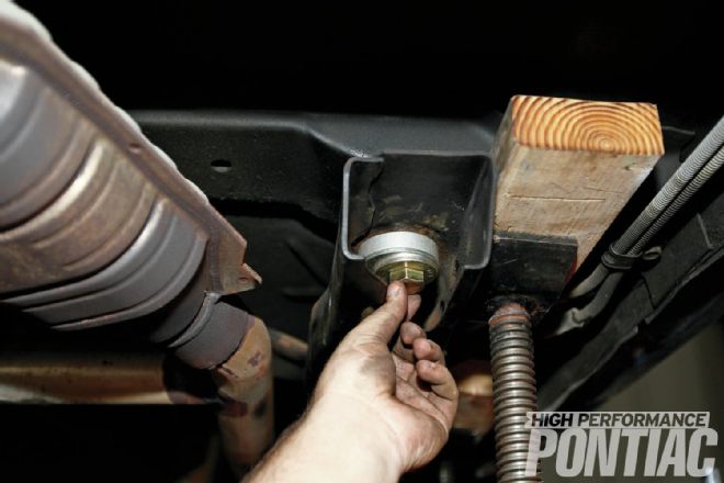
 20. The final two radiator-core support bushings were difficult to install, but after removing the front air dam, the Trans Am can be lowered so the battery and battery tray could be removed from up top with a socket wrench, 2-foot extension, and 3⁄4-inch socket.
 21. By placing a floor jack stacked with a piece of wood under it and raising it enough to remove the clamshell, we lifted the core support’s bottom. Once it was out, the bottom half of the PTFB bushing was installed, and a helper put the top piece in place so the bolt could be started and torqued with a 24mm wrench to 45 ft-lb after both bushings are in.
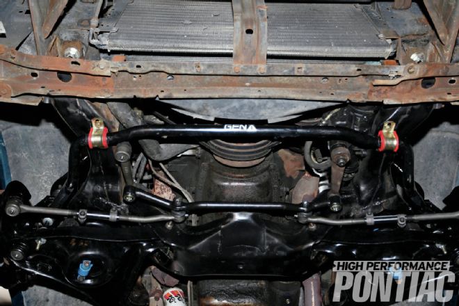
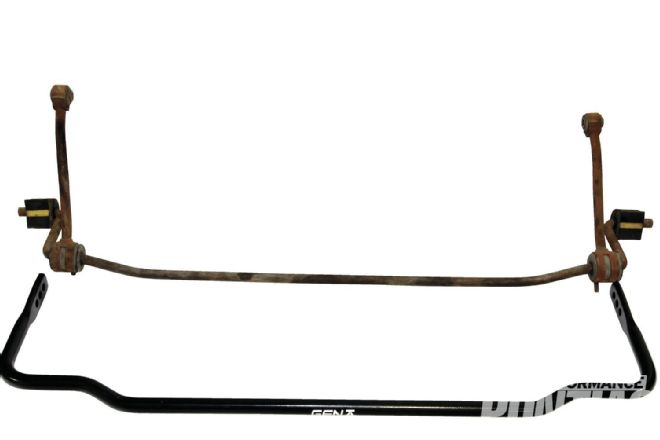 22. The front air dam, battery, and battery tray were reinstalled, and the rear sway bar was removed. Side by side, the factory bar with a diameter of 0.625 inches (5⁄8 inch) pales in comparison to the Gen II Racing adjustable 7⁄8-inch rear sway bar kit (PN 2CS-511, $289).
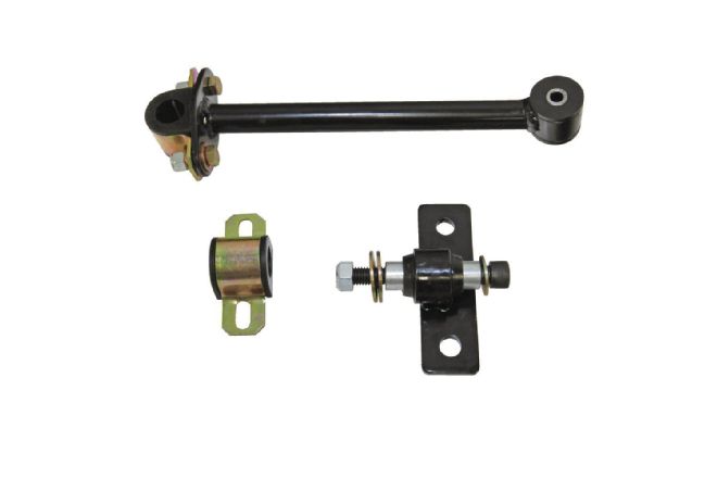 23. PTFB Rear Sway bar drop-link kit (PN 2CS-201,$139) is a significant upgrade over the stock sway -bar attachment hardware. When combined with the adjustability of the rear bar, it becomes the key to dialing in the car. Dave states, “The rear end is more sensitive to changes, so an adjustable bar allows us to tailor the rear end to be neutral.”
 24. The drop-link kit uppers were installed, and then the spring-plate inboard bolts were removed. The lower end-link kit was affixed under those bolts, and the sway bar was lifted up and fit into the upper and lower perches with the sway bar clamshell bushings on top and the washers and nuts onto the adjustable bar end. (We installed the sway bar in the center adjustment hole.)
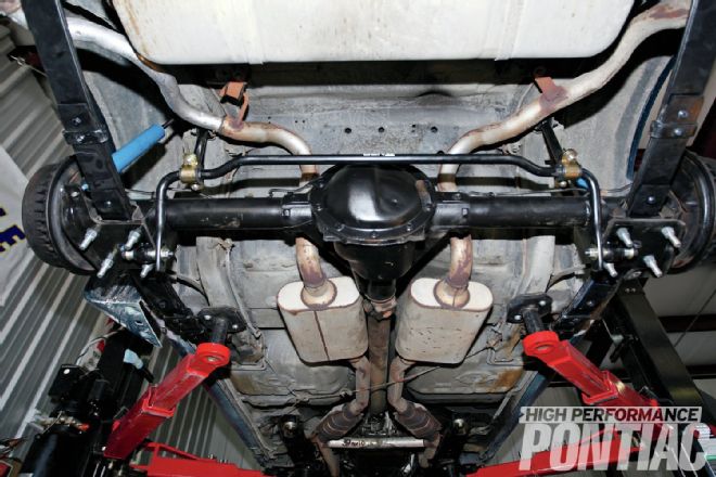
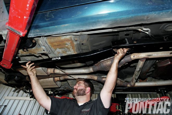 25. In order to install the subframe connectors, we needed a four-post lift to load the suspension. Mike demonstrates how the connectors will be installed. It’s as simple as lining up the front and rear of the connector to the subframe and drilling holes from the connector through the subframe, and then using the supplied bolt hardware to torque them down. According to Dave: “Body bushings and subframe connectors are paramount to stabilizing the chassis and providing a foundation to build upon. If you do one thing to your Second-Gen, purchase the pair under PN 2CF-004 for $259.”
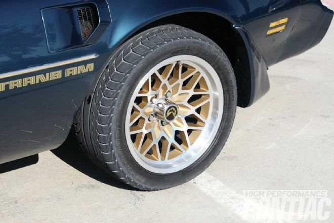
Wheels and Tires