Leaf springs are like iron cylinder heads. You can get them to work reasonably well, but unless class rules require you to run them, far more effective solutions are at your disposal. This explains why you won't see leaf springs beneath many front-running Pro Touring machines at a Goodguys autocross event. For g-Machines that must excel in both on-track performance and around town comfort, rear four-link suspension systems are where it's at. For a very reasonable price, they offer incredible improvements in handling, braking, and forward bite without sacrificing ride quality. Detroit Speed and Engineering has been offering four-link conversion kits for Camaros and Novas for several years, helping its customers stomp quite a few Mustangs around the autocross. It didn't take long before Mustang owners wanted to level the playing field, and began asking DSE to build parts for their cars. The company responded with its revolutionary Aluma-Frame front suspension system, and to ensure that the back end could keep pace with the high-tech frontend, DSE simultaneously engineered an all-new four-link rear suspension setup for 1964-70 Mustangs.
Considering leaf springs have been around since the days of the horse and carriage, it's somewhat miraculous that they're still chugging along hundreds of years later. A set of modern performance leaf springs matched with quality shocks make for a very cost-effective street combination. Furthermore, thanks to modern tire technology and traction-enhancing electronics, drag cars are now running 6-second e.t.'s on leaf springs. Even so, the biggest drawback of the typical leaf spring suspension in a muscle car is that the springs also serve as the control arms. That means that the springs are forced to endure all the acceleration, braking, and cornering loads of the rear suspension by themselves. This can lead to wheel hop during acceleration, and brake hop under braking, as the big and heavy rearend wraps up under load. Stiffer spring rates help resist these forces, but adversely affect ride quality.
The ideal solution to the problem is adding a set of control arms to assist in locating the rearend and support it when under load, which is precisely what a four-link accomplishes. Furthermore, replacing the leaf springs with coilovers yields much greater adjustability as well. For Mustang owners ready to take the plunge, DSE's QuadraLink kit includes a set of tubular upper and lower control arms, a Panhard bar, a sway bar, coilovers, a floorpan crossmember, and all necessary mounting brackets and hardware. Installation shouldn't be all that difficult for a seasoned veteran, but it does require some basic welding skills. To get a firsthand look on how it's done, we watched closely as DSE installed the QuadraLink on its 1966 Mustang fastback project car.
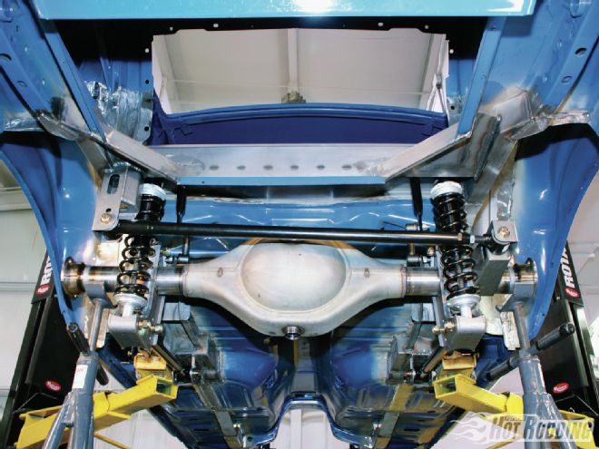 1. One of the most distinctive features of DSE’s Mustang QuadraLink system is its custom crossmember that’s integrated into the replacement trunk floor. The DSE trunk floor is taller than the factory piece, which allows mounting the top of the coilovers higher up in the framerail. The benefits are a taller coilover package that both increases suspension travel and orients the coilovers closer to vertical for improved efficiency.
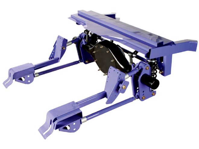 2. The Mustang QuadraLink system (PN 041731) fits 1964-70 Mustangs and lists for $3,000. The upper and lower control arms are both adjustable to help dial in the instant center and pinion angle, while a Panhard bar locates the rearend from side to side.
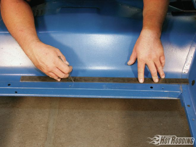 3. Since installing the QuadraLink requires a moderate amount of cutting and welding, the rear suspension, fuel tank, brake lines, fuel lines, and interior must be removed before any work can begin. Cutting out the factory trunk floor might seem intimidating, but it’s actually very straightforward. First mark the rear cutline by measuring 1.25 inches in front of the fuel tank flange.
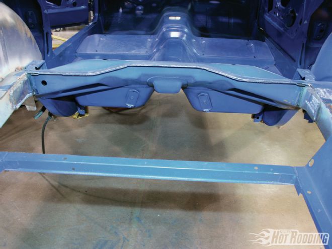 4. Once the rear cutline has been established, begin cutting from the center of the floorpan out toward the framerails on each side using a cutoff wheel. The front flange line of the trunk pan is clearly visible from beneath the car, which serves perfectly as the front cutline. Next, cut the sides of the trunk floor as close to the framerails as possible, then remove the entire pan.
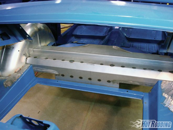 5. With the stock trunk floor out of the way, mock the replacement piece into position to check for fitment and trim the panel where necessary. The DSE trunk floor is one beefy hunk of 14-gauge steel that doubles as the crossmember for the coilovers. Not only does it substantially increase the structural rigidity of the chassis, but it also eliminates the need to weld a tubular crossmember to the factory framerails. In contrast, most factory floorpans are built from much thinner 18- to 20-gauge steel.
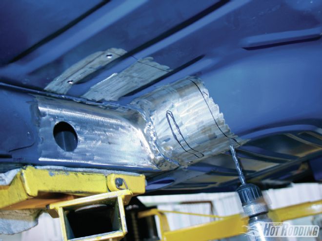
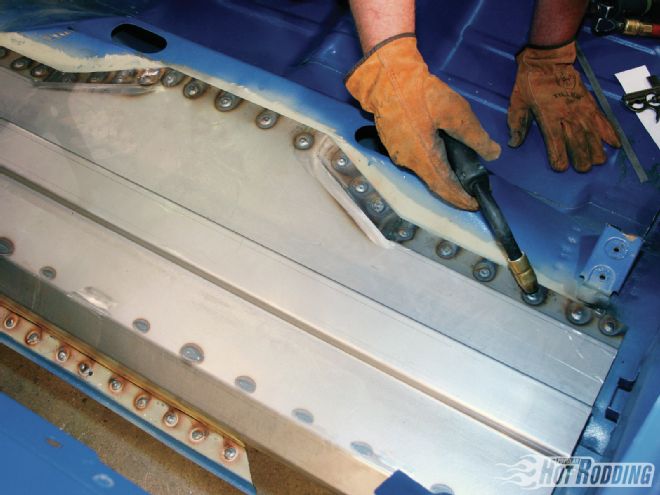 6. After punching holes into the front and rear flanges of the trunk floor spaced 1 inch apart, plug weld the floorpan crossmember to the factory body, then grind the surface smooth with an angle grinder. DSE used a Roper Whitney punch tool, but a drill will work just as well.
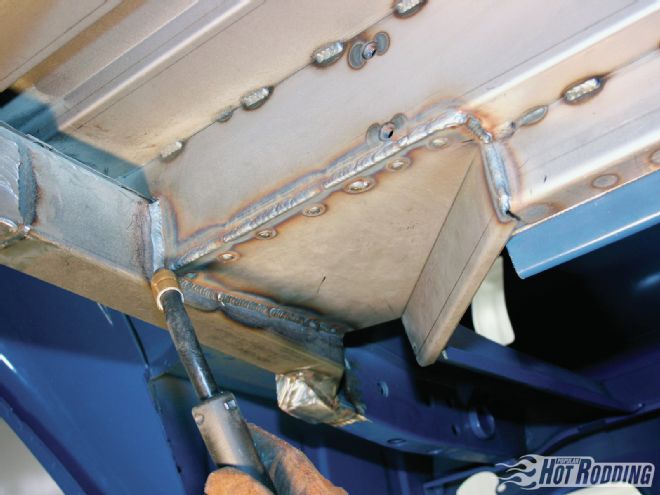
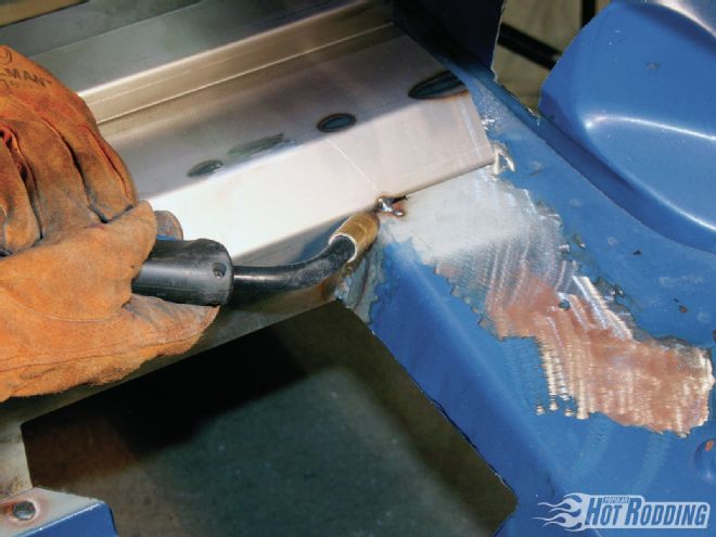 7. With the plug welding complete, seam weld the sides of the new trunk pan to the body. Remember to grind paint off the body to bare metal before welding, and apply a coat of weld-thru primer along the joints to prevent rust.
 8. To create a flat and solid mounting location for the Panhard bar bracket, the front corners of the fuel tank flange must be cut off and re-angled inward. Using the supplied DSE trunk closeout template, trace cut lines onto the floor and remove the marked sections of metal using a cutoff wheel.
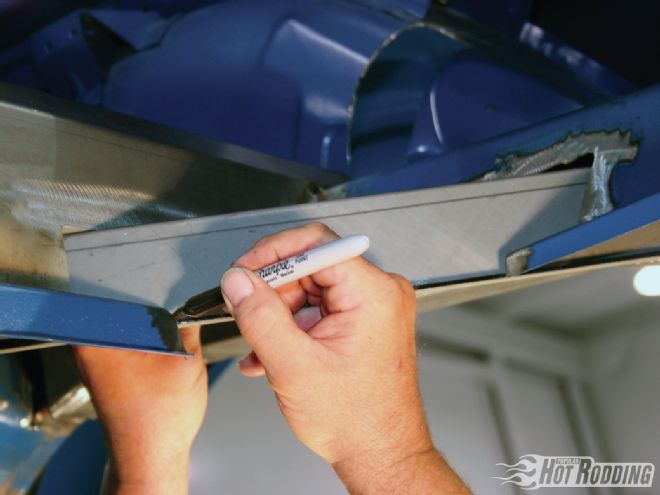
 9. To account for year-to-year variations in floor design, the DSE closeout panels are oversized, and must be trimmed into shape. After mocking the panels to the body, trace along the edges with a marker, then cut the panel accordingly using a cutoff wheel. Next, seam weld it into place.
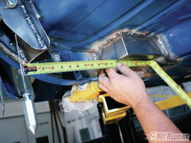
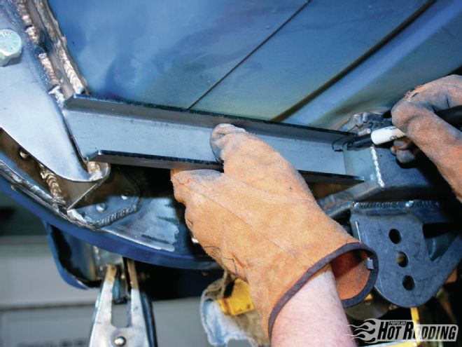
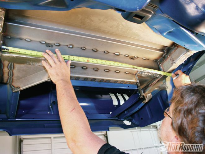 10. Locate the center of the trunk floor crossmember with a measuring tape, and measure 16.5 inches outward to the left and right to establish the shock bracket mounting locations. Mark these spots with a straightedge, as they determine where the outer edges of the shock brackets will mount.
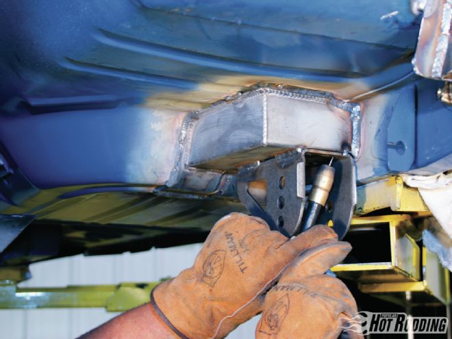
 11. Using the marks from the prior step as a guide, lay the shock brackets flush along the top and side of the crossmember before tack welding them for a trial fit. Make sure that the bolt reinforcement sleeves are positioned on the outboard side of the brackets before laying down the final seam welds.
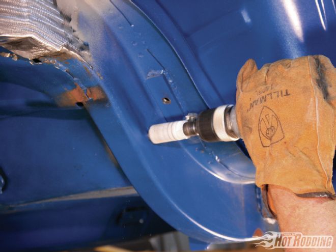 12. The QuadraLink kit includes an upper link mount location template that makes it easy to drill the frame in just the right spot. After marking the hole with a transfer punch, drill a small 3/16-inch pilot hole into the frame before drilling it all the way out using a 1-inch holesaw.
 13. Insert the crush tube into the upper control arm bolthole so that it protrudes 2.425 inches from the inboard framerail. Afterward, position the upper control arm bracket along the framerail and floor, and seam-weld it into place. The bracket assembly includes steel doubler plates that reinforce the framerail for extra rigidity.
 14. The lower control arm brackets mount to DSE-supplied torque box assemblies that attach along the edges of the framerail and the rear foot well hump. Mock the torque boxes into position, trace around their edges with a marker, and drill holes for plug welds (spaced 1 inch apart) into the floor across the entire mating surface.
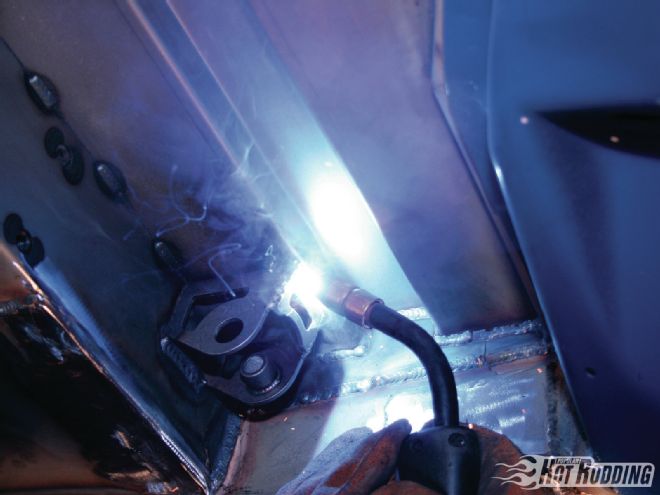
 15. Seam-weld the torque boxes to the body from the underside of the car and plug weld them to the floor from inside the car. Next, hang a plumb bob down from the upper control arm bolt, measure forward 14 inches, and mark the torque box to establish the inboard mounting location of the lower control arm bracket. The target bracket location will be roughly 3 inches inboard of the framerail.
 16. With the marks drawn in the prior step, line the rear edge of the bracket with the rear edge of the torque box. This should position the centerline of the bracket boltholes with the marks referenced off the plumb bobs. Tack-weld the lower control arm brackets to the torque boxes to check fitment, then seam-weld them in place.
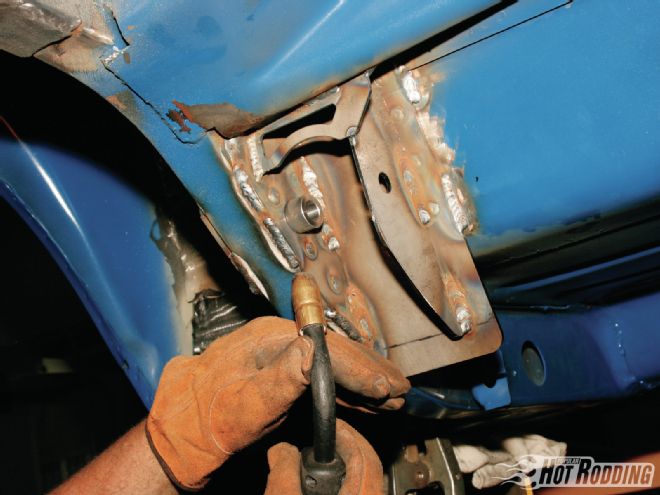
 17. The upper link mounting brace ties the upper control arm bracket to the torque box. The brace may need to be trimmed to fit depending on the year of vehicle. After confirming proper fitment, trace around the edges of the braces, then drill plug weld holes into the floor spaced at 1-inch intervals. Seam-weld the braces to the brackets and torque boxes and plug-weld them to the floor from inside the car.
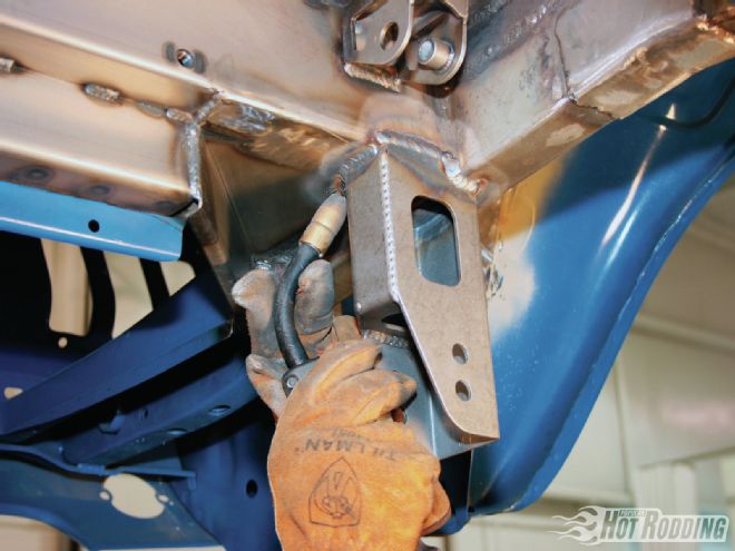 18. For easy installation, the Panhard bar bracket comes tabbed notched to fit at the intersection of the crossmember and driver-side framerail. Make sure that it’s sitting at 90 degrees before welding.
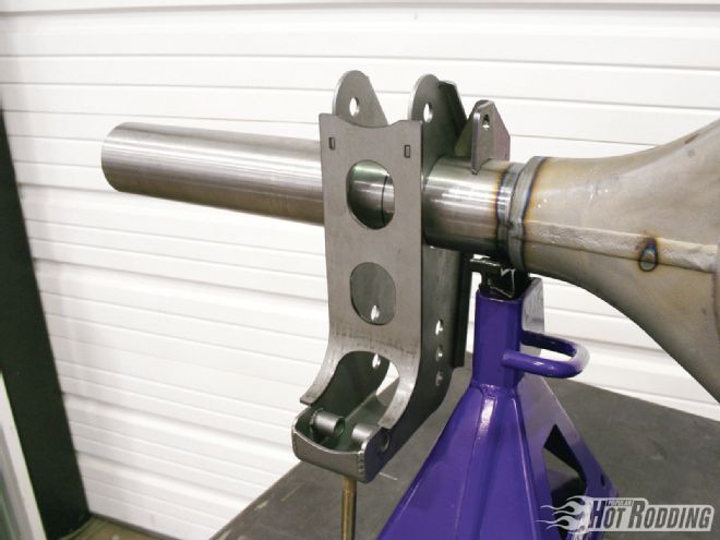 19. The QuadraLink rearend brackets slide over the axletubes and weld together in multiple sections. To locate them correctly, mark the axletubes 16 inches from the pinion centerline on the left and right axletubes, then position the center of the brackets at these marks. Using an angle gauge, set the bottom edge of the brackets at 0 degrees before welding them to the axletubes.
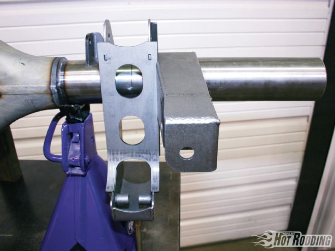 20. The Panhard bar bracket mounts directly adjacent to the passenger-side control arm bracket. Set the front edge of the bracket at a 90-degree angle, then seam-weld it to the tube. The sway bar endlink brackets should be positioned 1 inch inboard of the control arm brackets. Set them at 90 degrees before welding them down.
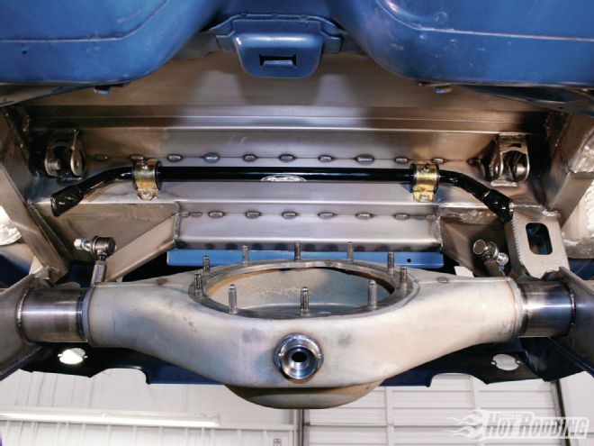 21. With the rearend assembly supported under the car, bolt the sway bar to the floorpan using the predrilled and tapped holes. Next, bolt the endlinks to the rearend before attaching them to the sway bar.
 22. Bolt both the upper and lower control arms into their respective brackets. Attach the control arms to the chassis first, followed by the rearend.
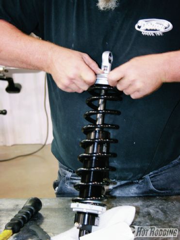 23. Assemble the coilovers on a bench before bolting them to the car. Slide the springs over the shocks, compress them slightly by hand, and secure them to the shocks by twisting the lock collars.
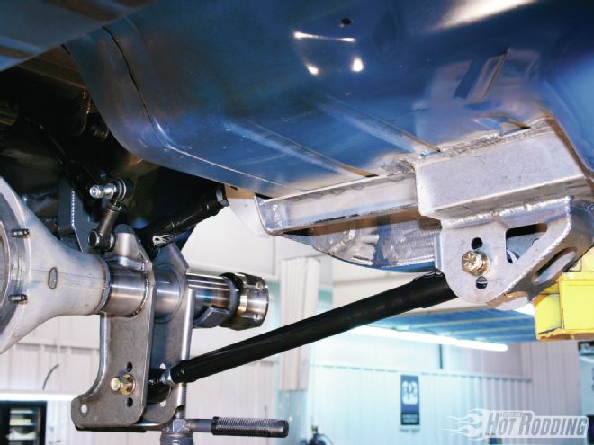
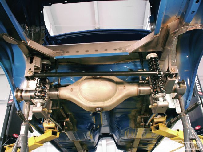 24. Bolt the bottom of the coilovers to the rearend and the top to the floorpan subframe. Finally, bolt the Panhard bar to the body, and then to the rearend bracket. One cool feature of the DSE Panhard bar is that it has multiple mounting holes, which allow adjusting the roll center.