Seems I have a long-standing habit of turning simple tasks into drawn-out, elaborate chores. And so it was with the shock mounts for the 1933 Tudor. Sorry, make that shock mounts with integrated headlight stanchions … custom-made ones at that.
Yes, I'm fully aware that SO-CAL Speed Shop has already gone to great lengths and offers F-100–style "dual-purpose" mounts. But here's the deal—my particular situation didn't quite fit their pre-made application's parameters. In other words, I wanted the ability to set my headlights in a specific position (lower and tighter to the car), not be limited to where the combo mount put 'em. Even the shock mounts themselves would require a bit of modification in order to accommodate the forthcoming notch we'll be adding to the framerail (for spring clearance).
So, we began our chore by acquiring SO-CAL's individual shock and headlight mounts (combined, they're the same price as the combo mount—minus the half day's labor required to fabricate the custom ones, of course!). Then, by installing a pair of Chassis Engineering hydraulic tube shocks, we were able to reconfigure the SO-CAL shock mount accordingly (which basically just meant lopping the lower mounting ear off and flipping upside-down so that it wouldn't interfere with the aforementioned 'rail notch).
Once the upper shock mounts were fashioned and installed, we performed similar surgery on the headlight mounts—cutting the base mount portion off, then shaping the stanchion to fit the shock mount at the desired position where we wanted the headlights to sit. This is where Jimmy White spent most of his time, carefully blending the two stainless mounts together as if they were made that way in the first place—like SO-CAL's...but different!
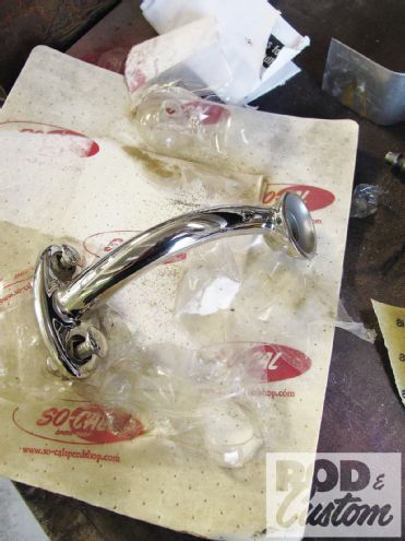
 1. Integrated headlight/shock mounts are no new thing. SO-CAL Speed Shop offers beautiful, polished stainless combo mounts, and Jimmy White’s fashioned his own for previous customers (like these shown here for an A-V8 project).
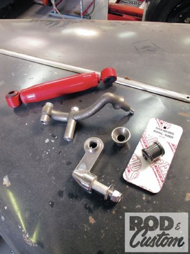 2. For the Tudor, we’re using SO-CAL’s plain F-100–style uppers and Chassis Engineering’s polished stainless lowers and painted steel hydraulic tube shocks. (The headlight cups were originally to be used prior to us acquiring a pair of SO-CAL headlight mounts from the swap meet.)
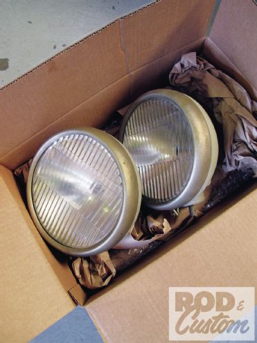 3. For the headlights, I scored these Parabeams a couple years back in Columbus. They’re somewhat similar to a stock ’33-34 light, but with subtle enough differences (like the shape of the bucket, for one). However, there is a drawback—the “ball” portion of the mount is reversed, so I’ll be swapping that out down the road once I locate a set of donor buckets.
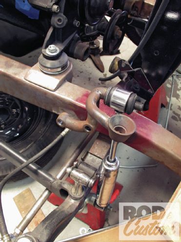
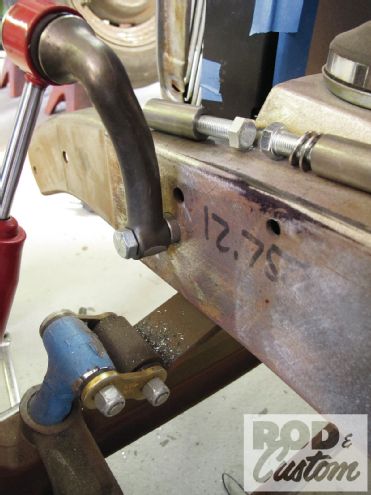
 4. Once the shocks were installed onto the lower mounts, Jimmy mocked the upper mount up onto the framerail. As you can see, the lower portion lands right where our forthcoming leaf spring notch will be, not to mention it’s right at the bottom edge of the framerail. So …
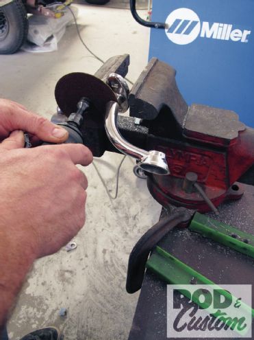
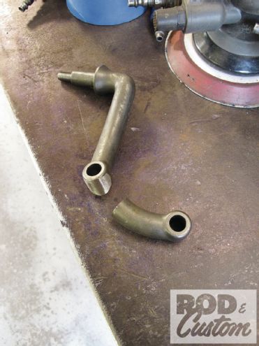 5. ...we accommodated that by removing the lower section. The severed stem was then reshaped (rounded out) so that it could be re-welded to the shock mount once its new position was determined.
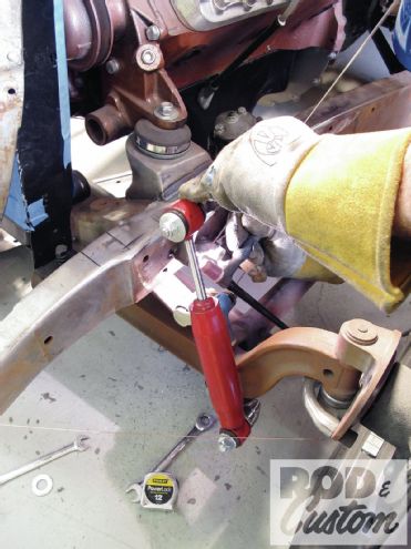
 6. To locate the main portion of the mount onto the framerail, the shock was set at ride height.
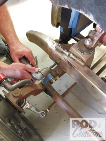
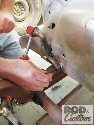
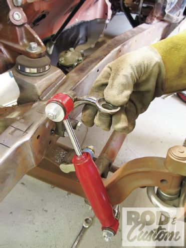
 7. The attached weld-in bung (the shorter of the two supplied with the mounts is meant for the upper hole) was marked accordingly onto the framerail.
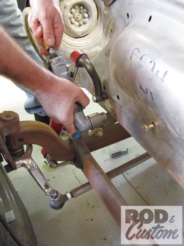
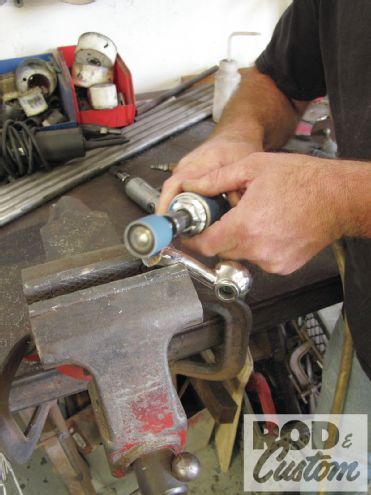
8. Starting with a pilot guide, White followed by using a Rotobroach with a pneumatic drill. The upper bung only requires drilling one hole; however, we may copy the lower later on by swapping for a longer bung that gets welded on both sides of the framerail.
7. The attached weld-in bung (the shorter of the two supplied with the mounts is meant for the upper hole) was marked accordingly onto the framerail.
8. Starting with a pilot guide, White followed by using a Rotobroach with a pneumatic drill. The upper bung only requires drilling one hole; however, we may copy the lower later on by swapping for a longer bung that gets welded on both sides of the framerail.
 9. Starting with a pilot guide, White followed by using a Rotobroach with a pneumatic drill. The upper bung only requires drilling one hole; however, we may copy the lower later on by swapping for a longer bung that gets welded on both sides of the framerail.
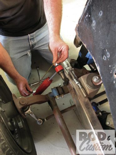
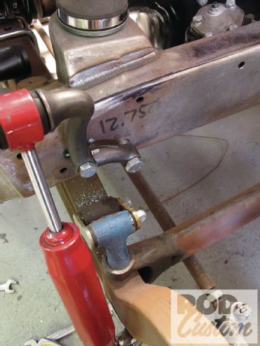
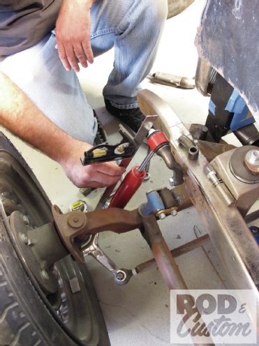 10. Prior to welding the bung (with a 1/4-inch stick-out, not flush), the angle and alignment of the shock in relation to the lower mount had to be set.
 11. As mentioned, White prefers to have the shock mounts stand off the framerail rather than sit flush, and thus has the bungs protrude from the ’rail 1/4 inch.
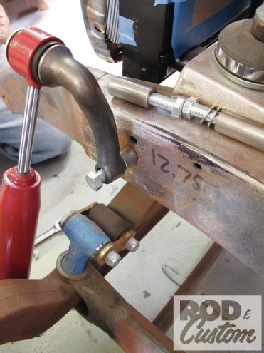
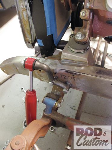
 12. The upper portion of the shock mount is tacked in place.
 13. The separated lower was repositioned and marked for reattachment.
 14. And at the same time, placement of the lower bung was determined.
 15. Once the holes for the lower bung were drilled out, the mount halves were aligned and united before the bung was tack-welded.
 16. Two hours (give or take) later, and we have our "new" shock mount. Now comes the fun part.
 17. Rather than fashion some headlight pedestals out of stainless bar stock and the cups I’d just purchased from Reid’s Rod Parts, I decided last minute to sacrifice a pair of SO-CAL headlight mounts I’d picked up from the swap meet some time ago.
 18. First, the base mounts of the headlight stands were cut loose (but saved for use later … maybe a future taillight mount?!).
 19. Next, with the Parabeam light position, we figured out how and where to attach the headlight perch to the shock mount.
 20. Some trimming and massaging later...
 21. ...and we found our perfect spot. But, in order to truly find the perfect spot for the headlight mount, we needed to actually attach with a tack weld and then attach the headlight to see how everything commingled, figuratively speaking.
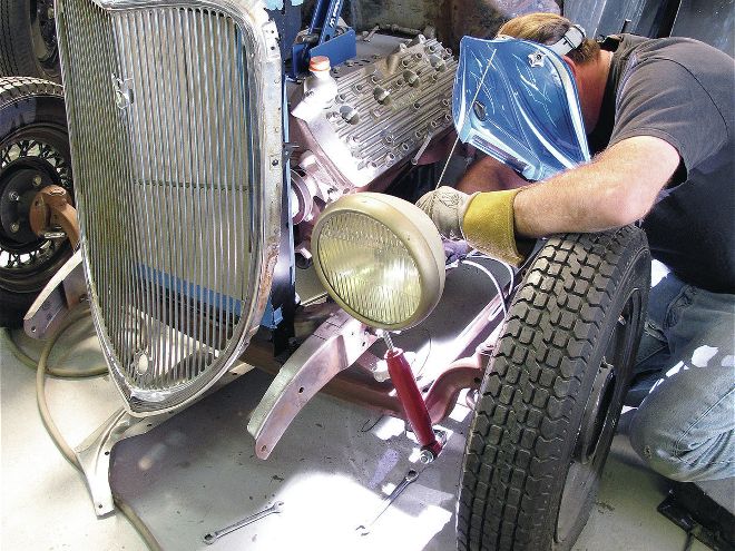
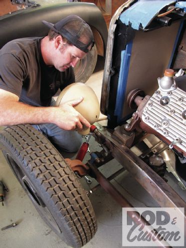
 22. With two sets of hands and three sets of eyes (Matt holding, me watching, and White positioning), the headlight was set and the perch prepared for welding.
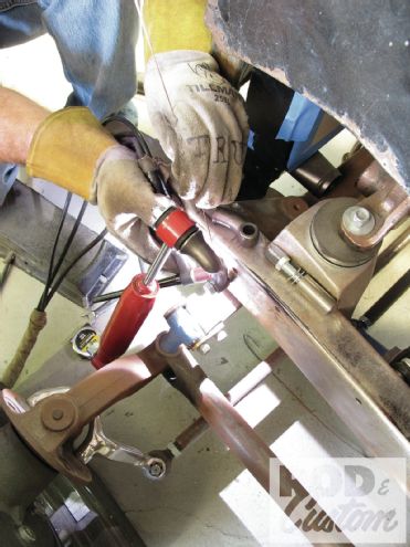
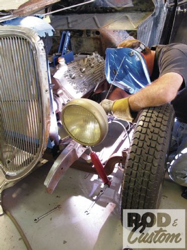 23. White welding in headlight after setting.
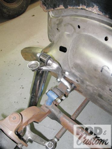
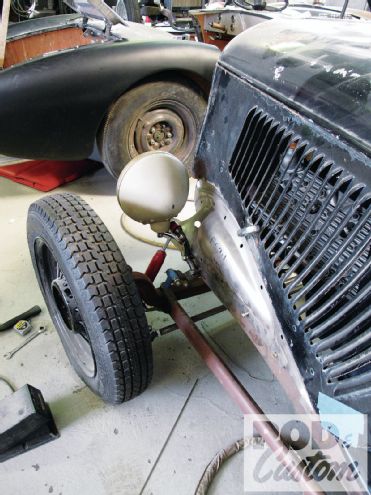 24. In order to ensure "perfect" positioning of the headlight, the hoodsides were closed and inner fender panels attached—from this angle, I was more than content with where things sat (from the front, it was even better).
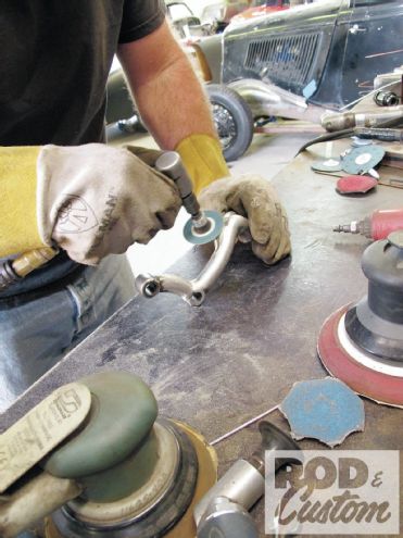 25. Once the headlight mount was attached and fully welded, White spent some time shaping the arm, blending it into the shock mount as if it came that way.
 26. Though much of White’s handiwork will be covered up by the looming headlight it will soon support, here’s the finished product. (Note that the shock mounts still need to be fully welded up.)
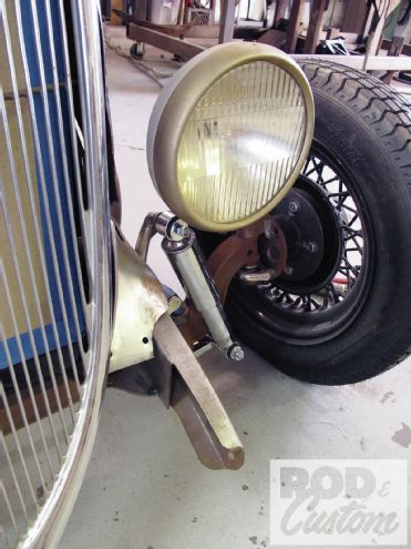
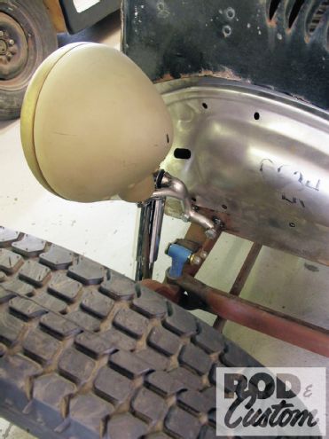 27. Low and tucked fairly tight to the body—just how I envisioned the headlight mounting from the get-go.
28. Often, covered shocks tend to interfere with front suspension components, thus the reason you see many fenderless rods with standard (uncovered) tube shocks. However, with the shock/headlight mount set up as such, I was able to fit a Pete & Jake’s covered shock without any interference.
27. Low and tucked fairly tight to the body—just how I envisioned the headlight mounting from the get-go.
28. Often, covered shocks tend to interfere with front suspension components, thus the reason you see many fenderless rods with standard (uncovered) tube shocks. However, with the shock/headlight mount set up as such, I was able to fit a Pete & Jake’s covered shock without any interference.