
Since a Pontiac V-8 is a pushrod engine (instead of being an overhead cam design), it afforded us the opportunity to explore a different rocker-arm ratio and determine its impact on power. As built, the Mule enjoyed Comp Cams full roller rocker arms with a ratio of 1.65:1. The stock ratio is 1.5:1 on Pontiac V-8 engines except for the Ram Air IV, V, and SD-421 engines, which used 1.65:1.
With the more aggressive rocker arms, the engine made just under 492 hp—stunning results for a mill that is able to produce that output on 88-octane Rocket Brand gasoline. It did not even require premium, let alone race gas. But being the hotrodders that we are, we are never satisfied—we always want more.
To this cause, we decided to see how the Mule would like a little less rocker arm (a lower numerical ratio). This might fly in contrast to conventional wisdom where bigger is usually better, but we had some bench racing theories that we wanted to test. More on that logic later.
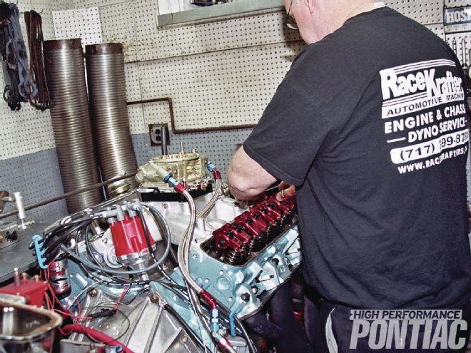 1 The day began with establishing a new baseline by making three pulls. The Mule was right there. Then Craig pulled off the valve covers and started to remove the 1.65:1 rocker arms from the exhaust valves.
As an aside to this, when the rocker-arm ratio is altered, it’s usually done on a production-style cylinder head such as our 6X castings by moving the pushrod cup closer to the pivot point of the rocker. If you were to measure accurately from the pivot center point outward to the pushrod cup, and then measure from the pivot to the end where the valve stem rides, you will see the difference. A rocker that is 1:1 would be equal in length from the pushrod cup to the centerline of the pivot, and from there to the valve stem contact area.
The other area we wanted to explore was the phase of the Comp Cams bumpstick. According to the cam card, the intake centerline was 106 degrees of crankshaft rotation, and Comp instructions specified installing the cam at 106 degrees, the straight-up position. A quick review of cam logic establishes that as the number goes numerically lower from the intake centerline, the cam position is advanced. In contrast, as the value goes numerically higher than the centerline, the cam is retarded. During the build of the Mule, Craig Wise from RaceKrafters Automotive Machine installed the cam exactly at the desired position of 106 degrees. This was confirmed with a degree wheel.
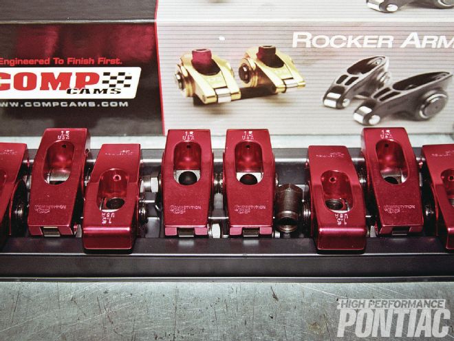 2 The Comp Cams full roller rockers in 1.5:1-ratio are the same color red as the 1.65:1 version, so we needed to reference the stamped ratio number to confirm we were installing the ones we wanted.
Thus our plan was as follows: Install Comp Cams 1.5:1-ratio full roller rockers (the same model rocker, just a different ratio), at first on the exhaust valves only, and test; then we would fit the 1.5:1 rocker arms to the intake valves too. This meant that both valves would have the 1.5:1-ratio rockers in lieu of the previously tested 1.65:1-ratio. Depending on the results, we would keep the rockers that made the most power and then alter the cam phase.
With the timing chain the Mule had, there were four positions to advance and retard the cam timing manufactured into the crankshaft gear of the cam drive. The cam can either be straight up (at the intake centerline), or advanced and retarded in 2-degree increments for a total of 8 degrees in each direction. This allowed a total range of 16 degrees—8 degrees advanced and the same amount retarded.
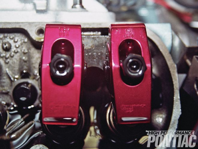 3 Here is a 1.65 on the intake with a 1.5 on the exhaust.
Cam phase or position usually follows a steadfast rule: Advancing the cam will improve bottom-end power at the sacrifice of high-rpm output. In contrast, retarded cam timing softens the bottom-end and increases the output at the upper rpm range. Some engine-builders like to advance the cam from the ideal position when the engine is new, since wear in the timing chain will cause the phase to retard, the logic being that the engine will self-compensate for wear by slowly retarding the cam timing to a straight-up position. As with any theory, you can chose to accept it or reject it, but there is validity in that concept if the engine is going to stay together for many years and be used in a street/strip car.
When discussing the rocker-arm ratio, it needs to be understood that you take the lobe lift of the cam (not the valve lift) and multiply it by the rocker ratio to provide the total valve lift. For example, if the cam lobe lift is 0.350-inch and the engine is fitted with a 1.5-ratio rocker arms, the equation would be 0.350 x 1.5 = 0.525-inch valve lift. The same cam using a 1.65-ratio rocker would yield a total valve lift of 0.577 inch.
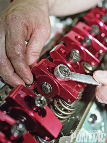
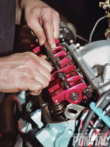 4 Craig ran all the valves and set the lash at zero with a quarter-turn of preload. The Mule did show a tendency for slow lifter pump-up after the rockers were removed each time. A few minutes of idling purged all the air, and the engine was nice and quiet.
This may bring a question to mind. Why not put all of the lift in the cam lobe and have a rocker arm that is 1:1? For the most part, that is the case with some OHC engines, or they may employ a ratio slightly more than that, such as 1.1:1. The logic behind using the rocker arm design to multiply the cam lift is due to limitations in the cam tunnel for lobe height, as well as to also control the velocity of the lifter as it follows the lobe up and down each side. Lifter velocity is a concern since it needs to operate smoothly over the entire lobe and offer a long service life. Due to these considerations, it’s best to obtain the desired valve lift through the lobe design and by manipulation of the rocker ratio to offer a gain in lift. It can be considered leverage over the valve stem.
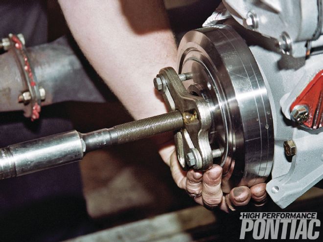 5 With the rocker testing complete, Craig pulled the Summit balancer and began to gain access to the cam timing gears.
A simplistic explanation of varied rocker-arm ratios is to think of opening the valve with a lever. The more travel that can be applied, the greater the valve lift at every point on the cam lobe. In addition, this allows the valve to be opened quicker (less degrees of cam rotation to achieve the same lift). The multiplicative effect is constant as the tappet rides the lobe of the cam from the base circle and up towards the nose.
If higher lift is good, then why did we think the Mule would like lower lift? That is a simple question with a complex answer. We surmised that it may be possible for the engine to like less valve lift on the exhaust side (where we changed the rocker arms first) due to the high ratio of exhaust flow when compared to the intake flow. This is called the intake-to-exhaust ratio. Many believe that you need a value of around 80 percent, while others feel that an engine can be more efficient with a ratio much less than that.
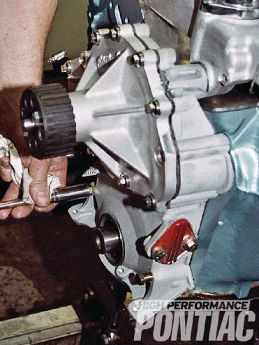 6 The Pontiac engine design allowed us to leave the water pump attached to the timing cover during the cam phase changes—a nice feature that saved some work.
Based on flowbench data derived from RaceKrafters, the Mule enjoyed a ratio of just around 78 percent. Our thought was if we limited the exhaust flow slightly, the engine may pick up power. We did not expect a huge gain due to the difference in cylinder-charge dynamics. We came into this test with trepidation. The Mule has already surprised us in good ways, so we thought we would try it.
The next stage of testing was to advance and retard the cam 4 degrees each way. The keyway allowed 2-degree phase changes. When employing a change that small, it’s usually very hard to quantify any value or detriment. We needed to make a change that was sufficient to move the dyno strain gauge enough to call it real. Since the cam was already in at 106 degrees, we chose first to retard it to 110 degrees. If the engine liked it, we would then play in 1- to 2-degree increments. The next step would be to go the other way and install the cam 4 degrees advanced to 102 degrees. The same protocol would then be followed based upon the Mule’s behavior against the Stuska water brake.
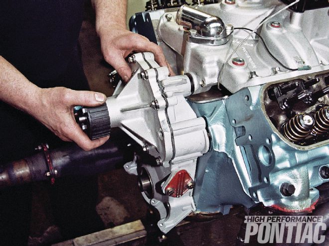 7 Craig carefully pried off the timing cover and did not tear the gasket, so were able to reuse it for the entire cam phase testing.
Cam-phase changes impact an area of engineering study that is identified as cylinder filling and emptying. The dynamics of the engine’s ability to breathe in and exhaust out are altered with the phase of the valve events. It’s an advanced science that often leaves many questions unanswered. The results of the dyno test are taken for face value and not agonized over. In engine guy parlance, we would say, “It liked it” or “It didn’t like that.”
Unlike a twin-cam engine, changing the cam position referenced from the intake lobe centerline also impacts the exhaust valve opening and closing with a like amount of crankshaft rotational degrees. That is why most modern engines employ more than one camshaft, especially when a variable valve-timing arrangement is used. This way the intake and exhaust valve timing can be altered independent of one another, and the cylinder filling and emptying dynamics can be tuned to perfection. With a traditional V-8 you don’t have that ability. You just need to try it and see what happens.
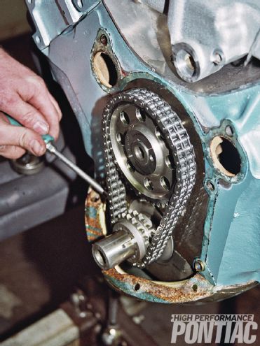 8 In as-built form, the cam was installed at an intake centerline of 106 degrees of crankshaft rotation, as per Comp’s specification. Craig carefully removed the timing chain so we could obtain access to the crank gear to change the cam phase.
The Results
With the engine guy vernacular for testing results previously established, I can say the Mule did not like anything we did to it that day.
It was baselined that morning on 88-octane Rockett Brand gasoline and produced an average 437.25 hp and 536.32 ft-lb from 3,300 to 5,300 rpm, with 32 degrees of total advance in by 2,900 rpm and #75 jets all around in the Holley.
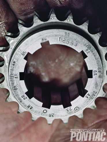 9 The Cloyes billet-steel timing gear and double-roller chain set allowed a good amount of tuneability with different notches in the crank sprocket. With the gear off, the timing marks and their description are clearly seen.
With the 1.5:1-ratio rockers on the exhaust valves only, the average dropped to 435.29 hp and 533.82 ft-lb. With these results, we normally wouldn’t have even bothered to change the intake rockers, but HPP wanted to provide the readers with more possible combinations. Now that both valves were fitted with the 1.5:1 rockers, the average power dropped slightly to 434.84 and 533.28 ft-lb. The carburetor and ignition tuning stayed the same for every test. There were no gains to be found.
Since the rocker arms proved to not enhance the engine, we removed them and installed the 1.65:1-ratio on both the intake and exhaust valves. Craig then made a pull to confirm the power was the same as before. The run looked as if it was a copy of our baseline that morning.
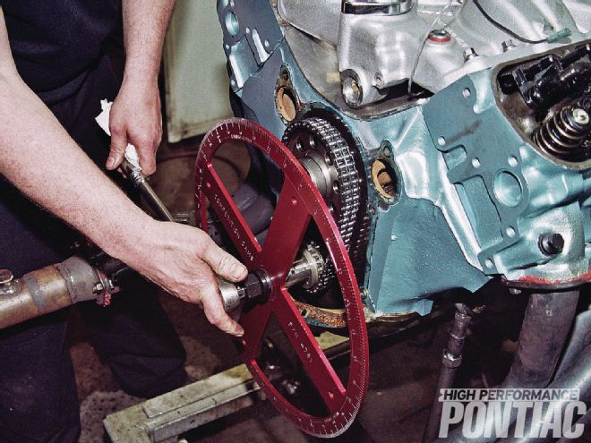 10 Each cam phase change was confirmed with a degree wheel using a piston stop to identify TDC.
With the front of the engine pulled apart and the rocker arms and pushrods off, we retarded the cam position to 110 degrees. The Pontiac did not like it. Average torque dropped to 524.44 ft-lb and average power went south to 428.45.
Craig then moved the cam to 4 degrees advanced from the original installed position of 106 degrees. It was now at 102 degrees. Once again, the Pontiac did not like what we did to it.
When analyzing the results, some facts need to be recognized. Our combination had excellent-flowing cylinder heads that did not experience port stall at the valve lift with the 1.65:1-ratio rocker arms. Thus, the lower-ratio rockers effectively limited the port flow, and in return, reduced the engine’s power.
In like fashion, the Pontiac required all the exhaust flow that it could get and did not want any less in that area. The results could have been different if the cylinder head did not flow well to a high lift or the flow actually dropped off. In that instance, the 1.5:1-ratio rockers may have showed a small power gain.
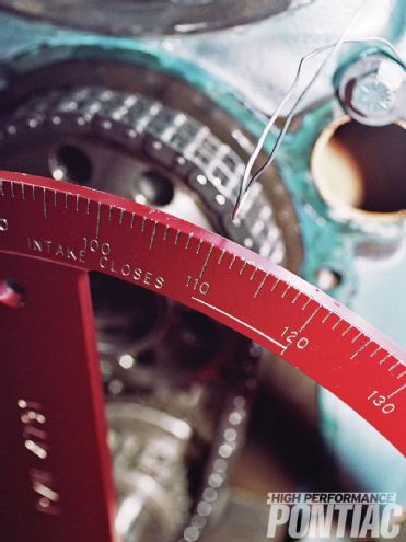 11 The first cam-position change was 110 degrees and then 102 degrees. Since the Mule did not like anything we did to it, Craig reset the cam back to 106 degrees for whatever testing is next.
When it comes to the camshaft phase, we tried to reinvent the wheel that Comp Cams already did an excellent job designing. The company is right on the money with the desired cam installation position of 106 degrees. But it must be noted that when Craig built the engine, the cam phase was checked and confirmed at the 106-degree suggestion. That in itself proves the need to check all camshaft installs with a degree wheel and not simply line up the timing marks and call it a day. The cam phase is critical to the engine’s performance and function.
Even though we found no additional power, we have confidence that the Mule has an optimized valvetrain with the current combination of parts. But with the plans we have for this mill, that will be changing soon!
HPP Engine Buildup Worksheet
Engine Displacement: 467 ci
Bore/Stroke: 4.185 / 4.250-in
Bore/Stroke ratio: 0.98:1
Rod/Stroke ratio: 1.6:1
Bottom End
Block: Stock ’75 455
Preparation: Cooked, magged, line-bored, line-honed, decks squared with BHJ, bored and honed with torque plates
Deck height: 10.205-in
Crank: Butler/Eagle forged
Preparation: Balanced, polished
Balancer: Summit Street/Strip, steel, elastomer, 6.610-in, SFI 18.1
Rods: Eagle forged H-beam, 6.800-in
Preparation: Pin-end honed to proper size, balanced, big end checked for proper size
Bearings: Clevite, plain shell, tri-metal
Preparation: Clean, check for proper clearance in rods
Pistons: Butler/Ross forged flat-top with valve reliefs
Preparation: Pin fit, check size, clean
Piston-to-deck height: 0.010-in below
Piston pins: Ross, 0.990-in floating, 0.155-in wall
Method used to retain pins in pistons: Spiro Locks
Rings: Total Seal, moly top; ductile second; three-piece oil; 1⁄16-, 1⁄16-, 3⁄16-in
Preparation: File-fit, clean
Rod bolts and head bolts: ARP
Balancing specs: Internal
Oiling System
Windage tray: Canton in pan
Crank scraper: Canton in pan
Oil pan: Canton Racing Road Race Series 5-quart, wet-sump
Oil pump: Melling M54DS high-volume
Heads
Casting number: 6X
Combustion chamber volume: 96.2cc
Maximum flow at 28 inches of pressure:
Lift Intake Flow CFM Exhaust Flow CFM
0.100
66
55
0.200
133
106
0.300
191
149
0.400
224
170
0.500
236
182
0.600
250
186
Compression ratio: 9.1:1
Valves: Manley SS 2.11/1.77-in
Angles used in valve job: Intake—45, 60, 75, and 82-deg, 82 is hand-blended into 75-deg; Exhaust—45-deg, 12mm radius
Retainers: Comp Cams, steel, 10-deg beehive
Keepers: Comp Cams 10-degee, 11⁄32-in
Valve Guides: K-line bronze liner
Valve Seals: Steel/Viton
Rocker Studs: ARP 7⁄16-in
Rocker Arms: Comp Cams aluminum full roller, 1.65:1
Pushrods: Manley 3⁄8x8.900-in
Cam
Brand: Comp Cams Xtreme Energy hydraulic roller
Duration At 0.050: 224/230-deg
Lift: 0.552/0.561-in
Centerline: 106-deg
Lobe Separation Angle: 110-deg
Installed Position: 106-deg
Lifters: Comp Cams roller
Valvesprings: Comp Cams Beehive
Seat Pressure: 137 lb/in
Open Pressure: 290 lb/in
Timing Chain: Cloyes double-roller
Induction
Carb: Holley 4150 HP 750-cfm, mechanical secondaries
Intake Manifold: Edelbrock Torker II
Ignition
Distributor: MSD Pro-Billet Ready-to-Run
Wires: MSD 8.5mm
Exhaust
Headers: Hooker
Primary Tube Diameter: 1.75-in
Primary Tube Length: 32-in
Collector Size: 3.00-in
Gaskets
Brand: Fel Pro
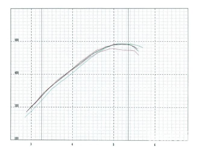 Corrected Horsepower
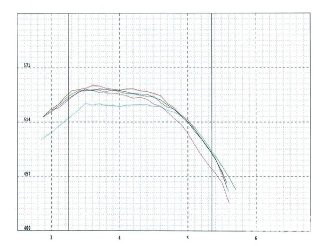 Corrected Torque
Here are the dyno charts that show the individual pulls. Red is the baseline, black is the 1.5 rockers on the exhaust, and green is 1.5 rockers on the intake and exhaust. Aqua is the cam retarded to 110 degrees, and purple is the cam advanced to 102 degrees.
Dyno Results
Configuration
Peak TQ
Peak HP
Avg TQ
Avg HP
As built
552.4
491.8
536.32
437.25
1.5:1 Exhaust only
549.0
491.4
533.82
435.29
1.5:1 Intake & Exhaust
547.7
492.2
533.28
434.84
Cam at 110-degrees
533.7
494.0
524.44
428.45
Cam at 102-degrees
548.6
478.0
527.64
429.65