Camshafts are one of the most confusing components in an internal combustion engine. What makes those lumpy bumpsticks even more confounding is the sheer number of grinds available, and then multiply that by flat-tappet hydraulic, hydraulic roller, and mechanical roller. With all those choices, how do you go about choosing a cam? While you could use the dartboard approach, in this age of computer simulators there's just no excuse for not arming yourself with the right information. That's what we're going to dive into here. To play out our dartboard analogy, consider that once you've read this story, that ancient finned dart has just become a laser-guided missile that will home right in on your next cam selection.
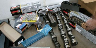
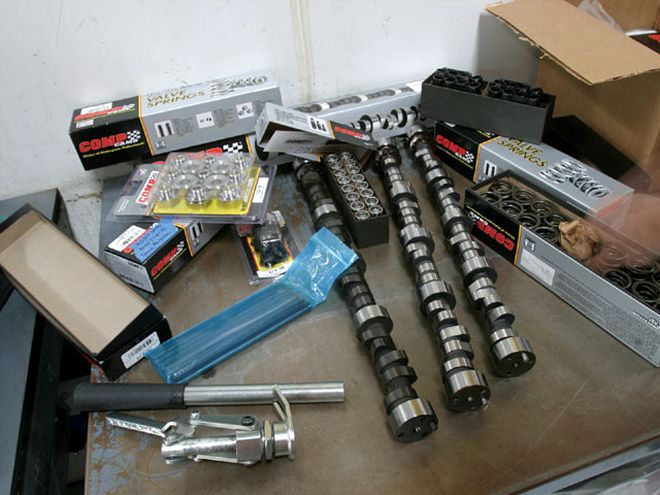 We chose three cams with almost identical duration numbers to use as our test mules to compare a hydraulic flat tappet against a hydraulic roller against a mechanical roller cam. The results were surprising.
It seems there is plenty of misinformation when it comes to comparing and contrasting a hydraulic flat-tappet cam with a hydraulic or mechanical roller. All three offer different valve lift potential, yet there should be a way to compare them on a level playing field. We huddled up with Comp Cams' chief cam designer, Billy Godbold, and came up with a camshaft from each of those different follower families that all share a very close kinship with duration at 0.050 inch, so that's what we chose as our common denominator. Now right away, you're going to look at the cam specs box and think we're off our rocker arms because the numbers don't match up. See, that's where it gets complicated. You're gonna have to read all the solid tech stuff to understand what we're doing here. Don't skip over the details or you'll miss something important. And while you're at it, eat your vegetables too.
Cam Basics
Since there are readers new to this magazine every month, let's quickly roll through some camshaft basics to bring everybody up to speed. There are several ways to evaluate any camshaft, so we'll start with the simplest: lift. A cam lobe is nothing more than an eccentric on a shaft that rotates to create lifter movement. Lift is created when the lobe moves off its base circle, pushing up on the lifter. This lobe lift is multiplied by the rocker ratio to create total valve lift. As an example, with 0.330 inch of lobe lift multiplied by a 1.5:1 rocker ratio, the valve lift would be 0.495 inch.
Perhaps the most informative portion of lobe specs is duration, which is expressed in terms of crankshaft degrees. Duration is also most often delivered in terms of either advertised duration or duration at 0.050 inch of tappet lift. To be totally accurate, any duration spec should be accompanied by the amount of tappet lift where the duration is measured. This rarely happens with advertised duration, but we can tell you that Comp Cams measures both its hydraulic flat-tappet and roller camshafts at 0.006 inch of tappet lift.
 Setting lash on any engine is relatively easy. The best procedure is to warm the engine and then use the exhaust-opening, intake-closing (EO, IC) procedure. With each lifter on the base circle, use a feeler gauge to measure lash at the rocker arm.
Where all this information can get confusing is when we move to mechanical lifter camshafts, either flat-tappet or mechanical roller, and talk about valve lash. Published cam specs are based on the numbers generated by the cam lobes and their effect on the valve. All mechanical lifter camshafts require a clearance between the rocker arm and the valve to account for expansion as the engine warms up. In the case of our XR286R roller cam, the intake lash or clearance is 0.016 inch with the engine hot.
Lash affects most of the published cam specs. The 0.576-inch gross intake valve lift figure on the cam card does not take into account the lash. This means we must use the equation 0.576 - 0.016 = 0.560 inch to come up with our actual net valve lift number. It's a small point, but worth noting for accuracy.
Lash also has an effect on duration. According to Comp Cams, the net change is that 0.001 inch of lash shortens the actual cam duration by 0.5 degree. So with a 0.016-inch lash on the intake, this effectively shortens the intake duration at 0.050 inch checking height by 8 degrees, creating a net duration of 240 degrees at 0.050 inch tappet lift. This explains why we chose a 248 at 0.050 roller cam, because the net duration after lash is actually 240 degrees.
CAM SPECS Cam Adv. Duration Lift Lobe Duration @ 0.050 Separation XE284 flat hyd., int. 284 240 0.507 110 PN 12-250-3, exh. 296 246 0.510 XR294HR, hyd. roller, int. 294 242 0.540 110 PN 12-43-8, exh. 300 248 0.562 XR286R mech. roller, int. 286 248 0.576 110 PN 12-772-8, exh. 292 252 0.582 Lash: 0.016 int., 0.018 exh.Why Roller Cams Are Better
This is some serious stuff, so you'll need to get rid of your normal distractions for a few minutes. It is possible to accurately compare a hydraulic flat-tappet cam with a hydraulic roller or even with a mechanical roller cam, but there are some important stepping stones to getting there. To begin with, all cams are rated for duration, based on the lobe profile and expressed in crankshaft degrees. For example, lift is expressed on the cam card in terms of valve lift using the stock rocker ratio. But what we should really be looking at with any style camshaft is the duration of valve opening. According to Comp Cams, the best way to rate a hydraulic lifter cam at the valve is to assume 0.004 inch of lifter piston bleed-down before the lifter begins to move the valve through the rocker arm ratio. In our chart the duration number 283 degrees indicates that the XE flat-tappet cam measures cam lobe duration at 0.006 inch of lifter rise (advertised duration), while the second column indicates that after 0.004 inch of tappet bleed-down and the lobe multiplied by the 1.5:1 rocker ratio, the duration at the valve is actually 282 degrees at 0.006-inch tappet lift.
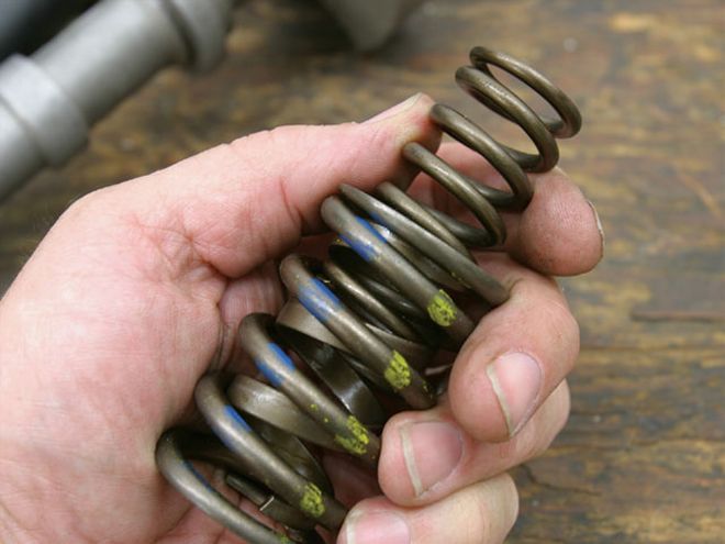
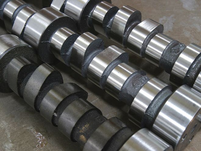 You can't tell much about a cam by looking at it. Even the two roller cams look much the same, but they perform very differently and require specific spring-pressure approaches.
We can use that same 0.004-inch lifter deflection figure to rate hydraulic roller cams. Notice that despite the fact that the flat-tappet and the hydraulic roller cams are only 2 degrees apart at 0.050 inch of lobe lift (240 versus 242), the hydraulic roller offers 5 more degrees of duration at the valve at 0.200 inch of lobe lift and an impressive 16 more degrees of duration at the valve at 0.400-inch lobe lift (from 107 to 123 degrees). This indicates the higher lifter speed capability of the hydraulic roller design over the hydraulic flat tappet. So while at 0.050 these cams appear the same, this number by itself is deceiving. Looking at a basic lift curve, the hydraulic roller achieves a given lobe lift such as 0.200 inch much more quickly and therefore creates more area under the valve lift curve. This means more air and fuel will enter the cylinder to make more power. Now let's look at the mechanical roller lobe.
Mechanical lifter camshafts are more difficult to evaluate because you should not use advertised duration as an indicator for several reasons. First, because of 0.016 inch of lash (clearance between the rocker arm and the valve), a lobe duration number measured at 0.006-inch tappet lift is meaningless because at a rocker ratio of 1.5:1, that 0.006-inch lobe lift number is worth 0.009 inch of movement at the rocker tip, which is still short of taking up the 0.016 inch of clearance. Even at 0.050 inch of lobe lift (duration at 0.050), this calculated number of 253 degrees of duration does not take into account the lash. Going back to Godbold's rule of thumb, every 0.001 inch of tappet lift is worth roughly half a degree of duration. In order to account for our rated 0.016 inch of lash, we must remove 8 degrees from the 0.050-inch duration figures, which means the 248 degrees at 0.050 is really 240 degrees and therefore exactly the same lobe duration at 0.050-inch tappet lift as the flat-tappet hydraulic camshaft. But notice the tremendous velocity the mechanical roller cam can generate throughout the entire lift curve, offering up a serious 197 degrees at 0.200-inch lobe lift. Compared to the hydraulic roller and flat-tappet cams, you can see why the mechanical roller is superior. At the extreme, the mechanical roller offers a staggering 21 more degrees of duration at 0.400-inch lobe lift than the hydraulic flat-tappet cam, and 5 more degrees than even the hydraulic roller (123 versus 128). What this means is that the intake valve is held open at the same valve lift for a much longer period of time within the cycle from when the valve first opens until it closes. This is why the mechanical roller cam can make more power than the hydraulic flat-tappet. Because of additional duration and greater lift, the mechanical roller lifter is traveling faster than its more conservative hydraulic counterparts, which is why lighter components and stiffer valvesprings must be part of the overall package.
284XE Hyd. Flat 294XE Hyd. Roller 286XER Mech. Roller Lobe Lift Lobe Dur. Valve Dur. Lobe Dur. Valve Dur. Lobe Dur. Valve Dur. @ 1.5:1 @ 1.5:1 @ 1.5:1 (w/ 0.004 (w/ 0.004 (0.016 lash) deflection) deflection) 0.006 283 282 294 292 (+10) 309 285 (+3) 0.015 268 271 276 280 (+9) 285 276 (+5) 0.050 240 250 242 253 (+3) 248 253 (+3) 0.200 153 190 164 195 (+5) 170 197 (+7) 0.400 - 107 - 123 (+16) - 128 (+21)
The numbers in parentheses for valve duration at 1.5:1 for both the 294XE hydraulic and the 286 XER are the number of degrees of difference compared to the 284XE hydraulic flat-tappet cam.
 Valvesprings need to be carefully matched to the specific camshaft in order to obtain maximum advantage from the cam. This is a dual spring with both an inner and outer spring plus a small, flat wire damper that is not counted as a spring.
Why You Need To Upgrade The Valvesprings
This chart is easy to understand once you know a little bit about valvesprings. Load at installed height refers to the amount of pressure in pounds created by the spring with the valve closed at a given installed height. The installed height is the distance from the bottom of the retainer to the spring seat location on the cylinder head. Load at maximum lift is the pressure created by the spring across the nose of the cam at its greatest valve opening. The spring rate is the amount of load in pounds created for every inch of travel the spring is compressed. If you know the load at both the closed and open points, you can determine the rate. Subtract the installed load from the open load and then multiply by the lift ratio (lift ratio = 1 divided by the max valve lift). Using the 939 spring as an example: 420 - 167 = 253 x 1.85 [1 1/4 0.540 lift = 1.85] = 468 pounds per inch (lb/in) spring rate. Coil-bind refers to the height of the spring when it is fully compressed. It's critical that the engine builder allow a minimum of 0.060 inch of clearance to coil-bind. We chose spring pressures higher than Comp's recommendations to ensure that the valvetrain would not go into valve float during testing.
Note the radical increase in seat pressure for the mechanical roller spring application. The hydraulic flat-tappet and roller springs both use a seat load of roughly 160 pounds. But when we get to the mechanical roller springs, the seat pressure jumps to 240 pounds at the same installed height. That's a 50 percent increase in seat pressure and a 59 percent increase in load at max lift. This is necessary in order to fully control the much higher acceleration rate and valve velocities achieved by the mechanical roller lobe working on the valves. As these opening and closing rates increase, they create much larger forces on the valve that must be controlled by the valvesprings.
Valvespring Load @installed ht. Load @ max lift Rate (lbs./in.) Coil-bind(in.) Comp PN 928, dual 153 @ 1.900 330 @ 0.500 354 1.160 Comp PN 939, dual 167 @ 1.900 420 @ 0.540 468 1.225 Comp PN 943, dual 240 @ 1.900 557 @ 0.575 551 1.150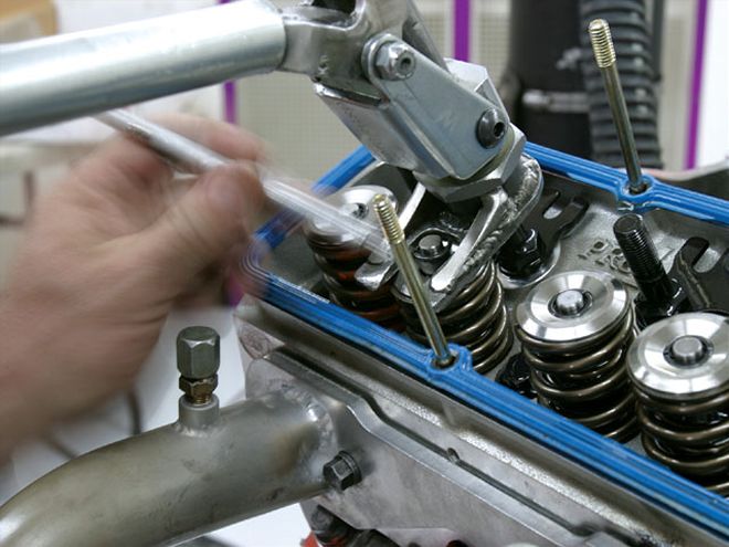 Each cam required a spring change to allow us to get the most performance out of each camshaft. Westech's Steve Brul kept the valves in place with compressed air and used a Moroso stud mount valvespring compressor tool to swap the springs.
Three Springs for Three Cams
It would be nice if all the moons and stars aligned in the engine-building world so that one valvespring would work for all applications. Perhaps back in the '20s that was the case, but not now. Because we have three completely different cam designs in a flat-tappet, a hydraulic roller, and a mechanical roller, all three require their own design valvespring. Spring pressure is critical to ensure that the valve is always controlled by the camshaft. Valve float is a common term referring to a loss of control, but for most engines the first sign of trouble is when the intake valve bounces off the seat on the closing portion of the lift curve. This allows cylinder pressure to escape back into the intake manifold, reducing power. Eventually the engine will begin to pop and bang, sounding like an ignition misfire, when in reality it is the valvesprings that have failed. Increasing the spring rate is the most popular solution to this problem, but another fix is to either reduce the rocker arm ratio or reduce the weight of the rocker arm side of the valvetrain, as with titanium retainers. Another excellent investment is thicker-walled pushrods. For small-block Chevys, 0.080-inch-wall-thickness, 51/416-inch-diameter pushrods are very common, but they do cost more. Stronger pushrods tend to deflect less, which reduces the pole-vault effect that can occur at high rpm when the pushrod bends and then launches the lifter over the nose of the cam.
The problem with increasing spring pressure with a flat-tappet camshaft is that too much pressure can literally wipe the lobe right off the cam. This is especially critical during camshaft break-in. For our engine, using the 928 dual springs required us to remove the inner spring for break-in and then install the inner springs after the cam had established its wear pattern. Even then we added extra insurance by using Comp Cams' break-in lubricant, which offers a higher zinc additive package to reduce initial wear on the new cam. When it comes to longer-duration hydraulic, flat- tappet, and hydraulic roller camshafts, the valvespring question becomes a delicate balancing act between maintaining sufficient spring pressure to control the valves at higher engine speeds and avoiding excessive spring pressures that can cause problems.
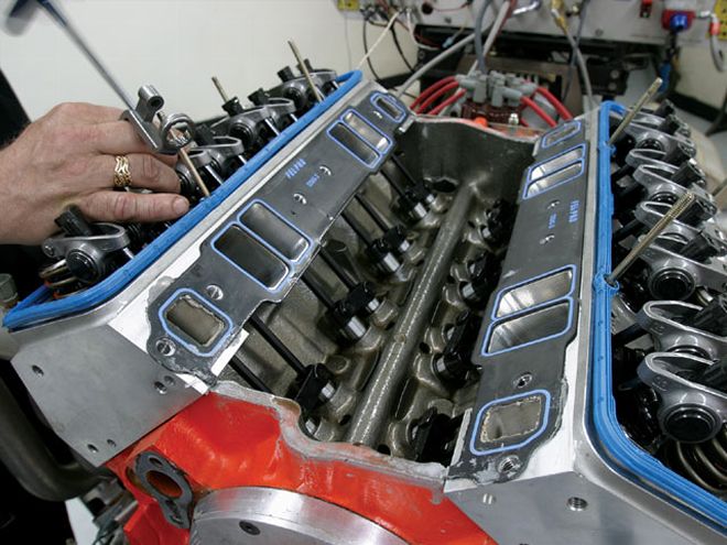
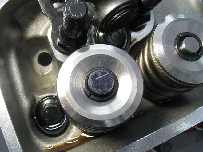 We also checked pushrod length with each cam change to maintain valvetrain geometry accuracy. Because the Dart heads use 0.200-inch-longer valves to fit stronger springs, this required custom-length pushrods for each camshaft. We set the pushrod length to create this position (arrow) on the valve tip with the lifter on the base circle of the lobe.
The beauty of a mechanical roller cam is that it allows the luxury of higher spring pressures, but there are difficulties here as well. Increased spring pressures place higher loads on the valvetrain, causing increased wear, not to mention abuse on those tiny roller bearings in the lifters. One reason for increased spring pressure is the higher engine speed that is part of the equation for a long-duration mechanical roller camshaft. We've included a short spring-pressure chart created with help from Westech's Steve Brul that we used to help us determine the best springs for each of the three different camshafts. These are numbers that Brul has found works for him.
An interesting question surfaced during this testing relative to how much spring pressure a hydraulic roller cam combination could withstand. Keeping this explanation short and simple, too much spring pressure does not really force the hydraulic lifter piston down, as is commonly thought. What really happens is that higher spring pressures tend to deflect the pushrod, which causes valvetrain separation at higher engine speeds when the pushrod pole vaults the valve past the nose of the cam. This clearance in the valvetrain allows the lifter piston to pump up. When the cam lobe returns to the base circle, the pumped-up lifter holds the intake valve open and causes the engine to lose power. Reducing hydraulic roller valvespring pressures to more manageable levels reduces pushrod flex and minimizes lifter pump-up.
SPRING PRESSURE CHART Lifter Style Seat Pressure Open Pressure (lbs.) (lbs.) Hydraulic flat tappet 150* 350* Hydraulic roller 200 400 Mechanical roller 220 575*After cam break-in. It is advisable to remove the inner spring on any dual-spring package when breaking in a new flat-tappet camshaft. This is not necessary with roller cams.
Test Time
With all this background tech information jammed into our heads, now it was finally time to put down the theory books and get our hands dirty. The small-block we decided to beat on was the healthy 383ci we used last month for the giant "Speed Parts Tested" cover story. The engine configuration for this test is a little different but includes 10.5:1 compression from a complete Lunati rotator assembly, a set of Dart CNC 227 heads, a Holley Keith Dorton single-plane intake manifold, and a Barry Grant 850 Mighty Demon carburetor. We started the test with the smallest cam, the Comp Xtreme Energy 284 hydraulic flat-tappet version matched up with a dual-spring package, titanium retainer, and the appropriate-length pushrods. The flat-tappet cam made respectable peak power at 507 hp at 6,200 rpm and 489 lb-ft of torque at 5,000. The beauty of a flat tappet is its decent power and great torque, all delivered at an affordable price. But now we were looking forward to ramping up the power numbers with the roller cams.
The hydraulic roller slid right in along with the taller Comp Cams hydraulic roller lifters. The taller lifters also demand shorter pushrods and, of course, a swap to a stronger set of Comp dual springs, which increase the spring load in order to help control the valves. As we expected, the hydraulic roller made more peak power than the flat tappet along with slightly more torque due to its more aggressive roller lobe design. This helps justify its increased cost. The hydraulic roller jumped the power up to 530 at 6,200 rpm while the torque also grew from 489 to 502 at 5,200. That's a solid 13 lb-ft increase of torque and 23 hp. Also note that both hydraulic cams peaked at almost the same rpm for both torque and horsepower. But all this did was motivate us to bolt in the mechanical roller.
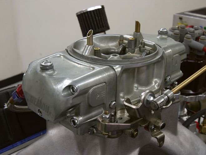 Our 383 small-block Chevy test mule consisted of a 383 with a Lunati forged crank, rod, and piston package along with Dart CNC 227 heads, a Holley single-plane intake, and this Barry Grant Mighty Demon 850-cfm carburetor. We used Westech's dyno 1 31/44-inch headers.
By now we were getting good at swapping cams, and the motor had barely cooled down before the new mechanical roller was in place and the springs and pushrods swapped once again. With 0.016-inch lash dialed in on the intake, the duration at the valve was exactly the same as the flat-tappet hydraulic cam, yet this mechanical roller setup rocked when it came to peak horsepower. Once we pulled the throttle handle, however, it quickly became apparent that while the peak horsepower was up over the hydraulic roller, the mechanical and hydraulic roller cam torque curves in the middle were almost identical, something we didn't expect. The mechanical roller's torque peak was actually down 6 lb-ft to 496 at 5,200 compared to the hydraulic roller, but made up the difference at peak horsepower with an impressive 539 at 6,600, which is up 9 hp over the hydraulic roller.
The best way to evaluate this test is to look at the power averages for all three cams. Because all three cams were chosen with the same duration at 0.050, there's not a huge difference in power averages between the three. The mechanical roller clearly owns the peak horsepower title with a stout 32hp advantage over the flat tappet. The mechanical roller also is up 12 hp and 11 lb-ft of torque average, which is a significant difference. But let's not overlook how well the flat-tappet cam performed, especially if we factor in the additional cost of either roller cam package. Of course, there's also the hassle factor of the flat-tappet cam, with both break-in and longevity concerns with current engine lubricants. But the power difference clearly points to the best power-per-dollar choice being with the flat-tappet cam. Looking at all the data, it would have been interesting to see how a flat-tappet mechanical cam would have fared in this test.
If you look at the graph of the three power curves, this may help with the concept of which lifter style cam is the correct one to use. Remember that the easiest way to make normally aspirated horsepower is to make the same torque at a higher engine speed. If you look at the flat-tappet hydraulic horsepower curve, it tends to flatten out at 5,200 rpm, while the two roller cam curves extend peak horsepower well past 6,000. If you plan to only shift your engine at 5,500 rpm or below, there's no reason to spend the extra money for a roller camshaft since all three cam torque curves up through around 5,200 rpm are very similar. The roller cams deliver far more valve control and rpm potential to make more horsepower. Also notice how the hydraulic roller tends to drop off at around 6,200 while the mechanical roller cam continues to make power up through 6,600. We think that this slight dip in the hydraulic roller curve is probably due to pushrod deflection. Since the price difference between a hydraulic roller and a mechanical roller cam is relatively small, there are opportunities for both styles of cam, especially if your plans include a shorter-duration roller cam that is not going to spin as high an rpm as these 240-degrees-at-0.050-duration camshafts.
What this test does illustrate is how critical duration is to the power curve since all three cams, regardless of lifter design, are very close in terms of peak torque. Peak horsepower changed the most between the three cams, but most of that was the change the mechanical roller made by pushing the peak horsepower up to 6,600 rpm. This is also of concern because to take full advantage of a 6,600-rpm peak horsepower point, it's generally required to spin the engine another 400 to 500 rpm past peak power to get the most acceleration advantage out of the engine. This means twisting this small-block to around 7,000 rpm. You'd better have a good steel crank, rods, and strong forged pistons if you're gonna spin a small-block 383 to 7,000 rpm!
Power By The NumbersTest 1 consisted of the 383 small-block Chevy with the flat-tappet hydraulic Comp XE284 cam. All other components for this test remained the same for all three tests.
Test 2 changed to the XEHR294 hydraulic roller cam and dual valvesprings.
Test 3 swapped to the XR286 mechanical roller cam and to a third, higher-load set of dual valvesprings with titanium retainers.
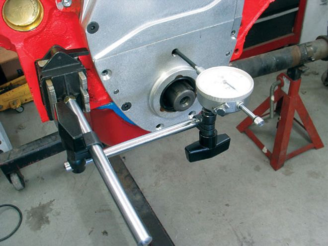 Before bolting the engine on the dyno, we also took the time to check for roller cam endplay for both the mechanical and hydraulic roller cams to ensure neither cam would move forward and retard the ignition timing. We used this Comp Cams three-piece small-block Chevy timing cover to make the cam swaps easy. It also features an access hole for measuring cam endplay.
The DIFF column represents the difference in power between Test 1 and Test 3.
TEST 1 TEST 2 TEST 3 DIFF RPM TQ HP TQ HP TQ HP TQ HP 3,000 420 240 421 241 425 243 +5 +3 3,200 429 262 429 262 431 263 +2 +1 3,400 430 279 430 278 434 281 +4 +2 3,600 436 299 438 300 437 300 + 1 +1 3,800 441 319 445 322 445 322 +4 +3 4,000 448 341 446 340 446 340 - 2 - 1 4,200 460 368 460 368 462 370 +2 +2 4,400 465 390 467 391 472 395 +7 +5 4,600 477 418 476 417 481 422 +4 +4 4,800 487 446 491 449 489 447 +2 +1 5,000 489 466 500 476 494 470 +5 +4 5,200 489 485 502 497 496 491 +7 +6 5,400 482 495 496 510 493 507 +11 +12 5,600 467 498 487 519 486 518 +19 +20 5,800 456 503 478 528 476 526 +20 +23 6,000 443 506 463 529 464 530 +21 +24 6,200 429 507 449 530 452 534 +23 +27 6,400 409 499 431 525 442 539 +33 +40 6,600 378 475 415 522 429 539 +51 +64 Avg. 450.7 412 460.7 423 461.7 424 +11 +12 Peak 489 507 502 530 496 539 +7 +32
Note: The average columns take into account power numbers every 100 rpm, which are not listed in this chart.
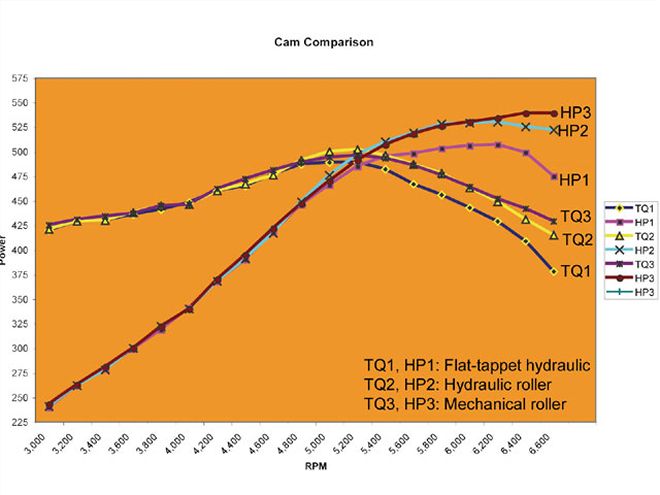
Power Curves
Note how all three camshafts create almost identical power curves through 5,000 rpm. By 5,200 rpm, you can see the hydraulic flat-tappet cam begin to nose over while both rollers continue to make similar power up to 6,000, where the mechanical roller takes over to make the most peak horsepower.