 The rocker arm is one of the most important components in the linkage between the camshaft and the valves. In a race motor, the geometric and component design can offer gains in efficiency and horsepower.
To call the Crane Cams shaft-mounted "Quick-Lift" design rocker arms new would not be entirely accurate. To say they have burst onto the scene and have created a lot of excitement among high-performance engine builders would be more true.
This concept has been contemplated and fiddled with for a long time, beginning with Smokey Yunick and his accomplished assistant, Ralph Johnson. Let's face it. Smokey fiddled with every component on the engines, but he thought there was really something to be gained with the geometry of the rocker arms. Ralph now works in the secretive R&D division of Crane Cams and has been instrumental in the development of this design from the very beginning.
The reason this particular design was so late in coming is the technology of materials and the design equipment needed to build and test these new rocker arms had not yet been invented. A lot of engineering, research, and development went into the current design. It didn't just pop out of the CNC machine and go to market-not by a long shot.
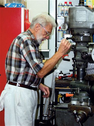 Ralph Johnson worked with Smokey Yunick to develop better geometry for the common rocker arm. That early work has paid off and can now be utilized by all racers due to advances in materials and machinery.
The new design has several cutting-edge features that are attractive for high-performance applications. The first feature we will talk about is the material itself. The rocker is made from a special alloy of aluminum that is stronger in the heat range in which it must perform.
A New Material Years ago, major aluminum companies developed high-strength aluminum products for the aerospace industry. The operating temperatures that an aircraft encountered, for design purposes, were from 100 degrees F all the way down to subzero temperatures. This heat range was at the opposite end of the spectrum from that experienced in racing applications. Modern racing engines operate in the range of 250-300 degrees F.
When Crane design engineers first asked for data on aluminum's strength at higher temperatures, the companies that produced high-strength aluminum did not have any information to share. Subsequently, the top suppliers of special alloy aluminum tested and developed compounds that were actually stronger in the higher heat ranges than at ambient temperatures. Crane now utilizes those aluminum compounds in the manufacture of their rocker arms.
The new rocker body is made from an extruded billet of a new alloy variation of 2024 grade aluminum that has only recently become available. According to the company's claims, it is "approximately 30-percent stronger at 300 degrees F than other comparable alloys.
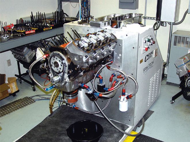 The Spintron test machine has allowed Crane Cams to efficiently develop new valvetrain components. Here, the new Quick-Lift rocker arms get a workout through simulation runs for Dragsters, Sprint Cars, and Stock Cars. The unit's "Laser Valve Tracking System" was ideal for testing the rockers.
Advanced Geometric Design The installed ratio, or what I will call the "net rocker ratio," or NRR, is determined by measuring the travel of the valve divided by the travel of the valve lifter as the cam cycles through its motion. When we know this ratio, we truly know what the rocker is doing throughout the cam rotational cycle. The measurement of the distance from the centerline of the rocker shaft to the tip of the pushrod and then to the end of the valve stem does not represent the true picture of rocker ratio.
The measured effective rocker ratio (measured at the rocker), or ERR, must take into account the angle of the valve stem and pushrod-to-rocker arm alignment. If these angles become more or less than 90 degrees throughout the cam cycle, and that is exactly what happens, then the ratio is necessarily changing.
In order to determine the true rocker ratio, you must measure, in increments of degrees of camshaft rotation, the travel distance of the valve divided by the travel distance of the lifter. This ratio can and does change in most applications.
Depending on the design and construction of the rocker arm, the ratio can start out less than the "advertised," or stated ratio and then reach the stated ratio at mid-cycle. On the back side of the cycle, as the valve is closing, the ratio decreases until the valve is closed. This type of design offers less flow of air/fuel mixture during the whole event.
Another design might have the true rocker ratio start and end, through the whole cycle, at the stated ratio for the rocker. This represents an improvement in rocker arm design, but the Quick-Lift design has been shown to be even better than that.
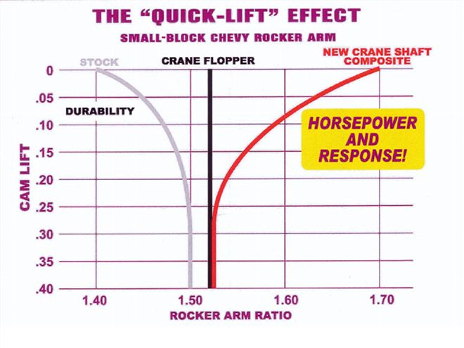 This chart shows a typical older design of rocker arm on the left, such as the original stock-stamped rocker.
The Quick-Lift design actually increases the rocker ratio at the start and end of the valve opening cycle. The mid-cycle ratio is the stated ratio. The rocker ratio is increased by utilizing basic geometry and arranging the position of the contact points for the valve and the pushrod through the cam cycle so that the NRR may start out higher by + 0.20.
This means that a rocker that reached a NRR of 1.50 at maximum valve lift may start out around 1.70 and end with the valve closing at 1.70. The advantage of this is the air/fuel mixture gets a better start entering the chamber, allowing better flow characteristics and increased total volume that is available for combustion. In short, this adds up to more horsepower.
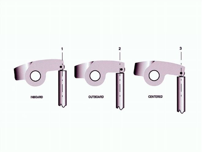 Throughout the cycle, especially at full spring compression and full loading on the components, the rocker tip is centered on the valve end.
Extensive testing and redesign has yielded an improved design that shows an increase in horsepower as well as the ability to endure. Anytime we can raise the power output while maintaining endurance, we have moved ahead in the performance game.
A New Bearing Design The benefits don't stop with material and geometry improvements. The new rocker arm has an all-new bearing design that has been perfected and proven in competition. It is technically a surface "friction" bearing, but that term does not do it justice. What this new bearing design does is reduce friction and wear over the common needle or roller bearing design.
Truthfully, it took a lot of R&D to find just the right combination of materials and refine the process of manufacturing these bearings, but the product has proven itself. The design of these bearings for this application just makes sense.
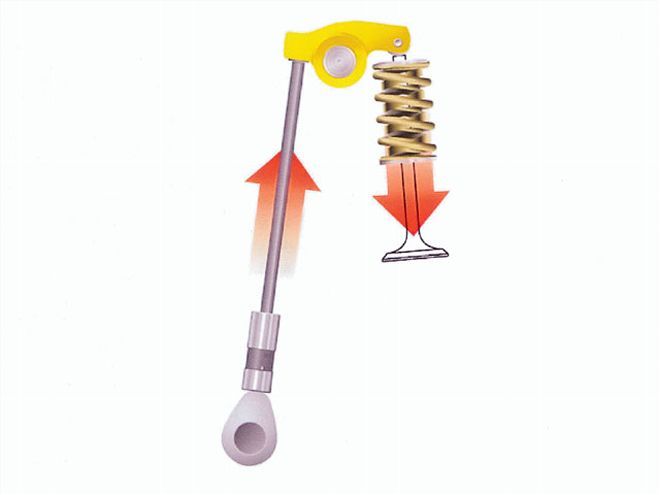
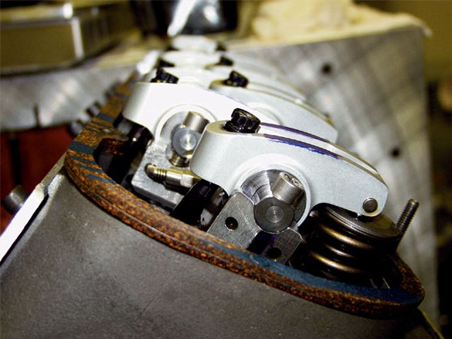 Note the angle of the pushrod to the angle of the valve lash adjuster screw. At rest, there is an angle. But at full cam lift, the pushrod and adjuster screw are inline.
The high pressures and unique motion of the rocker arm necessitates a design that can deal with those functions. The new PMC bearings provide increased surface area to spread the loads produced by stiff competition valvesprings while maintaining a layer of lubricating oil at all times to keep friction to a minimum. Less friction and more lubricating oil means less wear and tear.
A needle bearing exerts a lot of localized load on the bearing race and rocker shaft surface, creating heat. The bearing also acts as a squeegee and wipes most of the oil off the mating surfaces. It has to. In contrast to this tendency, the new PMC bearings spread the load over a large surface, and there is nothing to wipe the oil off the surfaces.
A layer of oil always remains between the bearing and the mating surfaces to lubricate and cool the components. This means that these new rockers can withstand higher open than ever before without failure.
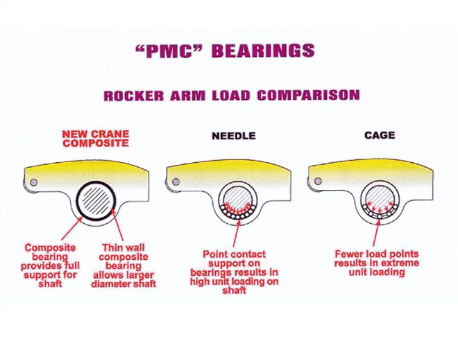 Poly-Matrix Composite (PMC) bearings are superior to needle or caged bearings in a number of ways. There is reduced friction, heat, and vibration. The actual bearing surface that supports the loading is far greater with the PMC bearings.
The shaft size is larger, too, due to the fact the design does not need roller or needle bearings. The shaft in the new design is 51/48-inch in diameter. This provides even more bearing surface for reduced load per unit of area and less friction.
One More Thing To complete the redesign, another key change was made that deviates from some previous designs. The angle of the valve lash adjuster to the pushrod was changed so that when the valve is at full lift, the valvespring is at full compression; the spring pressures are the greatest; the pushrod is inline with the adjuster; and the pocket is perfectly matched with the end of the pushrod.
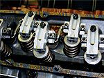
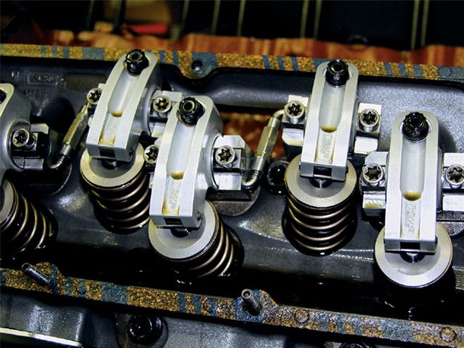 The rockers are located laterally on the valve stems through the use of adjusters (shown at the center between the rockers) that link the rockers. These also keep the rockers in place and properly centered at all times.
This may not sound like a big deal, but it is definitely an improvement. Lateral loading of the adjuster screw can alter the hole shape, and the adjuster can then become loose. Since most of the load is at high lift, it does no good to be inline while the valve is at rest and then misaligned at full lift. Oiling is improved, too, when it is most needed, and that is when the system is under full load.
Looking at all of the changes and why they were made, one top engineer who teaches the art of high-performance engine building remarked that he had finally seen a rocker arm that was designed correctly. We think this new rocker arm design will change the way engine builders value a rocker arm geometry that improves basic flow through the engine. The secret is out for those who were previously aware, and soon everyone will want to take advantage of these unique advances.