Carb spacers have been around almost forever and still, their modus operandi is largely shrouded in mystery. Part of this lack of understanding stems from the fact that they are so easy to test for function that it is often easier and quicker to run a test than to figure out how they might (or might not) work on any given application.There are six factors governing carb spacer function. We will take these one at a time and see how each influences the output of an engine.
Tip One-Spacers Enhance Access To Carb CFMIn many instances, a given intake manifold and carb combination is more suited to low and midrange power than it is top-end output. Part of the problem here is usually that such setups are two-plane manifolds with inadequate carburetor cfm for the size of engine involved. Any time a two-plane manifold is used, any particular cylinder sees only two barrels of that carburetor through which to draw air. Adding an open spacer between the intake manifold and a carb allows any particular cylinder to see all four barrels of carburetion. This move, in essence, turns a two-plane manifold into a very crude single-plane manifold. In so doing, it invalidates the strong point of a two-plane manifold, namely its good vacuum characteristics and strong midrange output. These assets come about because there is no robbing by one cylinder from another since, in a 180-degree two-plane manifold, no induction events overlap.
Many stock GM manifolds from the Quadrajet carb days (and there are still millions of these around) can benefit greatly from the use of an open spacer. But simply adding a spacer can create its own flow problem. Air exiting the carburetor enters the plenum created by the spacer. So far so good, but when it has to exit the mini-plenum created by the spacer, it must negotiate the sharp manifold face from the throttle-bore edges to go down into the manifold. Having such sharp edges can negate the potential airflow advantage of using the spacer in the first place. The key here is to provide a radiused entry into the manifold in order to make the most of the increased access to the carb CFM. This could be ground onto the manifold, but in the example shown, it was put on the spacer to conform to race regs. The nearby sidebar on pg. 62 shows how a composite 1-inch spacer made of four .25-inch-thick gaskets was made to pay off during the testing of a dirt car motor built to highly restrictive rules.
Tip Two-Spacers Increase Air DensityWhat the tests in Sidebar 1 don't reflect is the change in air density due to the fact that a spacer made of insulating material can reduce carb temperature. The reason is that the tests were carried out on an intake manifold, which, due to some serious insulation, ran at virtually ambient temperature. In most instances this would not be the case because an as-manufactured intake manifold would run much hotter. By using a spacer with good insulating properties, carburetor body temperature can be considerably reduced. This in turn means that the fuel is cooler, and as such, less turns to a volume consuming vapor. With more fuel in fine droplet form instead of vapor, there is more room in the intake manifold for the induced air. Because an insulating spacer reduces carb temperature, it leads to an increase in volumetric efficiency. Whether this pays off on the dragstrip or not, is questionable. It all depends on the time the carburetor has had to heat-soak. In practice we find that it takes about a minute for cool fuel from the tank to overcome the carb body heat it has soaked up from previous runs. On the other hand, if you're running a road course, there's enough time for the carb to cool down and deliver extra power. How much extra power? That's somewhat of a variable, but certainly on a typical 350hp to 400hp engine, 2 to 4 lb-ft of extra torque throughout the rpm range is common, and numbers as high as eight are not unheard of.
Tip Three-Spacers Help Displacement-to-Plenum Volume RatioWhether you're contemplating running a tunnel ram or a single four-barrel open-plenum race-style intake, there is a certain optimum plenum-volume-to-cylinder-displacement ratio for the rpm range involved. Most intake manifolds, especially single four-barrel ones, are manufactured with a plenum volume deliberately made too small for the typical engine they are going to be put on. This is done so that those manifolds will also suit the smaller displacement versions of whatever engine they are intended for. For instance, a Victor Jr. has a plenum volume better suited to about a 300-inch engine rather than to the 350-inch engines they are most commonly used on. This being the case, a spacer brings the plenum volume into line with what we may expect would be required for a 350-inch engine. From this you can see that for any given open-plenum manifold, the bigger the engine, the greater the spacer thickness needs to be to generate the plenum volume required.
Looking back on some old dyno tests done with a 302-, a 350-, and a 400-inch small-block Chevy, all with Victor Jr. intakes, illustrates the trend. On the 302, some marginal gains were seen with a .5-inch open spacer, but a 1-inch spacer cut output, especially midrange torque. On the 350, best results were found with a 2-inch spacer. Its use produced up to 6 more horsepower at peak and as much as 14 more at 750 rpm over peak power. On the 400-inch engine, a stack of three 1-inch spacers produced the best results. Here the engine was so desperate for extra plenum volume that peak power went up by over 11 hp.
The optimum plenum volume is not only interconnected with engine displacement, but also the rpm the engine makes peak power at. If all the aforementioned engines had peak-power rpm at say, 1,000-rpm higher, they may have needed to have as much as 1 inch of extra spacer to access that power.
Tip Four-Spacers Increase Carb CFMIf designed as one of its primary functions, a carb spacer can be used to increase the cfm delivered by the carb. It does this without necessarily affecting the carb's ability to adequately atomize the fuel. An example might serve best to show how to use a carb and a flow-enhancing spacer. Let's say the engine needed to have 780 cfm. Rather than use a 780-cfm carb and an open spacer, an engine builder may elect to use a 750 carb with the spacer shown above. This can augment the flow, thus giving a 750 carb the same or similar airflow capacity when on the engine. The usual result here is that the engine will make the same top-end output, but have a better low and midrange due to having a little more active carburetor. Another example of the use of this type of spacer is when race rules prohibit the use of a carb any more than a certain cfm. For instance, there are many race classes, both on the dragstrip and circle/road track events that call for a maximum of 750 cfm of carburetion. Adding a flow-enhancing spacer often allows such a carb to deliver another 15 or more cfm.
Tip Five-Use A Spacer To Suppress Flow ReversionPressure pulses generated by the valve opening and closing events and tuned lengths of both intake and exhaust can often produce unwanted flow reversions in the intake. These offending flow reversions considerably upset the carb booster function. What happens is that as the flow reversal goes through the booster in the opposite direction, it draws fuel. When the flow about-faces and returns to the carb via the booster, it draws yet more fuel. This results in the mixture-during the reversion event-becoming very rich, thus killing a good deal of horsepower. There are a number of means to suppress reversion. One of these is to build something approaching a mechanical diode into the intake system. That is, the system will have good flow into the engine but bad flow out of it. Some spacers are designed to do just this. They are normally used on very highly tuned engines that have monster cams and turn equally monstrous rpm. A Pro Stock-style engine would fall into the category we're dealing with here.
There is, of course, one type of reverse-flow that is not that uncommon that no amount of anti-reversion redesign is going to deal with. I'm referring to a nitrous backfire. Unless steps are taken to the contrary, a nitrous backfire can easily bend all the throttle plates in the carburetion system. You may think you've built a system that guards well against a backfire in the first place, but it only needs one mishap to cause a nitrous backfire. Keith Wilson of Wilson Manifold fame came up with a simple solution to this problem: spacer plates with burst panels.
Since we've arrived at the subject of nitrous injection, it's well worth mentioning that (for the most part) nitrous systems make more horsepower with a larger volume under the nitrous spray bar. Although it is highly dependent on the type of plate system used, it has often been found that spray bar systems tend to work best when they are two or more inches away from where the runners start in the manifold plenum.
Tip Six-Spacers Improve Fuel Atomization And DistributionThe spacer above successfully serves in two roles: Firstly, it has strong anti-reversion capabilities. Secondly, by putting appropriately positioned cutouts in the intruder tubes, it can redistribute fuel to achieve more even air/fuel ratios amongst the cylinders. The lengths of the anti-reversion intruder tubes shown in the drawing are a little exaggerated in length to make a point. In most cases, their length would be between two thirds and half their respective diameter. The way these intruder tubes function to redistribute the mixture is simple: Adjacent to the runner of whichever cylinder is lean, a triangular cutout is made in the intruder tube. In practice, the cutout acts like a magnet on the wet-flow fuel on the walls of the intruder tube. This causes more fuel to exit in the area of the cutout than around the rest of the periphery of the tube. It is this extra fuel that feeds the potentially lean cylinder to bring the mixture around to something near correct. This style of spacer can only be used with manifolds having a tall plenum. If you try using them in a short-plenum manifold they can introduce their own set of mixture distribution problems. For the most part, this type of spacer works best when used on top of a conventional 2-inch or more open spacer.
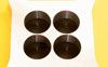
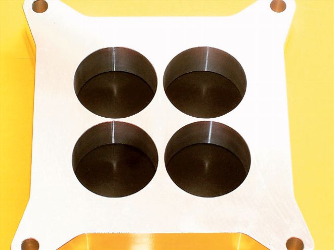
Q-Jet QuickieShown below is a stock iron Chevy Q-Jet manifold as was used on millions of small blocks. Note the sharp edges making up the corners between the carb bore holes and the carb mounting pad. Without the aid of a radius, these are really bad for airflow. In this case, race rules prohibited manifold airflow mods, so a .25-inch-thick gasket with the edges (arrow) radiused was used to ease the problem.
This gasket was then used with three open gaskets (i.e. one large, near square hole) to form one composite spacer 1-inch-thick (the rule limit). A larger 1.5 to 2 inches might have been better. As the dyno shows, without the benefit of the radius at the manifold face, the simple open spacer (O/Spr) did not work. With the radius four-hole gasket against the manifold and three open gasket/spacers on top (Rad/Spr), there was a worthwhile gain over the no-spacer baseline.
CHEVY Q-JET WITH GASKET SPACER B/line O/Spr Rad/Spr B/line O/Spr Rad/Spr Gain Tq. Gain HP RPM TQ1 TQ2 TQ3 HP1 HP2 HP3 4,000 386.4 380.8 387.6 294.3 290.0 295.2 0.9 0.7 4,250 386.3 384.4 387.2 312.6 311.1 313.3 3.7 3.2 4,500 376.3 373.2 380.0 322.4 319.8 325.6 1.0 0.9 4,750 371.6 368.9 372.6 336.1 333.6 337 3.6 3.4 5,000 358.7 355.9 362.3 341.5 338.8 344.9 1.7 1.7 5,250 347.7 342.2 349.4 347.6 342.1 349.3 3.0 3.2 5,500 333.1 328.5 336.1 348.8 344.0 352 1.9 2.1 5,750 318.7 314.1 320.6 348.9 343.9 351 2.3 2.7 6,000 297.2 292.5 299.5 339.5 334.2 342.2 3.4 4 6,250 279.8 276 283.2 333 328.5 337 3.6 4.4 6,500 258.6 255 262.2 320.1 315.6 324.5 2.4 2.5 Ave. 337.7 333.8 340.1 331.3 327.4 333.8 2.5 2.6Wide OpenShown below are the results of a test I ran a while back on one of my mule motors. This used a spacer style as per the Ultra Pro piece shown in the photo. I am using this as an example because it demonstrates that if the engine really needs more plenum volume, it really pays off to supply it.
Not only are the results of the before and after test worth scrutinizing, but the overall figures obtained from this 355-inch small-block Chevy. Although only a hair off 530 hp and a very strong 466.5 lb-ft, this was no high-dollar race engine. In practice, it had enough low-end capability to be used on the street as it would pull cleanly down to 2,000 rpm. Parts for this engine included .030-over pistons from Ross that had previously seen use in two of my previous engine builds. In spite of running the equivalent of at least one Daytona 500, they were still in near-perfect condition. These were equipped with Total Seal rings and delivered a 12:1 compression ratio. The heads were a set of relatively old pieces from Dart, which had undergone basic home porting and worked like a charm. The cam (280-seat duration single-pattern) was a well-used entry-level race roller that Comp did for me 15 years ago. Ditto for the valvetrain. With the equally old Comp stainless steel rockers, the delivered valve lift was about 625 thousandths. For induction, my slightly reworked Holly 750 carb (which flowed about 800 cfm) was used.
This sat on a Victor Jr. that Keith Wilson personally reworked for me years ago, and it has yet to be beaten for power on engines in the 500-plus-horsepower range. Although it does not apply to the same degree with a Q-Jet, both Holley and Barry Grant Demon carbs require the mixture to be re-optimized after a spacer is installed. This is especially so if the plenum volume has substantially increased. Usually when a spacer is installed, the mixture will lean out to the extent that the main jets will need to be increased two to maybe as much as four sizes.
355CI SMALL-BLOCK CHEVY