 The Ford 2300 engine has proven itself reliable for four-cylinder racing classes and delivers strong performance at 7,500 rpm.
In our January issue, we introduced you to a Mustang Mini Stock project undertaken by Steve Smith Autosports and Esslinger Engineering. Our previous effort focused on the suspension, and now we look at the engine that puts the power to the ground. This buildup is also covered in a video called Ford 2300 Engine Building, and the complete buildup can be found in the book, Building the Mustang Ministock. Both are available from Steve Smith Autosports Publications, 714/639-7681, www.stevesmithautosports.com.
Wherever you find Mini Stocks, you are likely to find the Ford 2.3 OHC engine in the pit area. This powerplant has proven itself worthy of the challenges of the four-cylinder racing wars. It has been offered in a number of Ford and Mercury products since 1974 and remains plentiful. A 2-liter version was introduced in truck lines in 1983. Bore diameter is the only difference between the two engine types, meaning all parts are interchangeable.
With any engine project, a solid foundation is necessary. When considering a Ford 2.3 block, look at the junction of the breather boss to the block (on the left side). This is prone to cracks if the block freezes. The valve covers and pan should be pulled to look for cracks, heavy sludge, or cylinder wall wear. Connecting rods should be inspected for discoloration. The cylinder bores should be free of scratches.
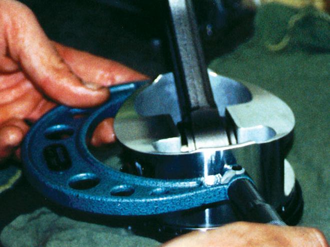 A micrometer is used to measure the piston diameter 90 degrees from the pin centerline. With this number and the expected piston-to-bore clearance, cylinder honing size can be determined.
If it has been faced with excessive heat, the head will crack between the exhaust seat and the intake seat. The cracks are generally not visible to the naked eye and require magnafluxing.
Look for physical damage to the engine. Any damage could indicate it ran out of oil at some time, causing internal woes. A damaged crank pulley could indicate severe internal damage from a blow to the front of the engine.
The block and head should be disassembled with freeze plugs and threaded oil gallery plugs removed. The engine should be hot-tanked and then cleaned with high-pressure steam and a good degreaser. Use compressed air to blow dry the block.
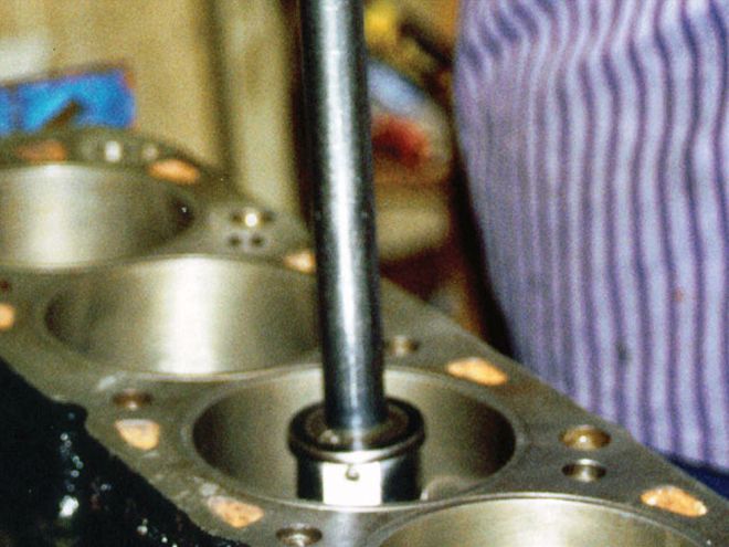 A dial bore gauge can determine the finished size of the cylinder.
Since castings don't have a uniform thickness, sonic testing is a good idea. You can determine if the block is good enough to proceed, especially if overboring is involved. Your block will face several machining operations, including align-boring the mains, milling the block deck, boring the cylinders, and finish-honing the cylinder bores.
A used block needs overboring to clean up the cylinder walls and to ensure the bores are perfectly round. It is not advisable to overbore a 2300 block much beyond 0.040 inch due to thin cylinder walls. Too much boring can cause cylinder wall flex.
Before the cylinders are honed, piston-to-bore clearance must be set. Check the piston manufacturer's recommendations. Clearance for racing will generally fall between 0.003-0.005 inch. A closer fitting piston will support the rings better and seal better. However, a piston that is too tight will result in friction and damaging heat.
 Studs with steel support straps can outperform main cap bolts, especially in high-rpm applications.
To find clearance, mate each piston to a cylinder and number them according to their cylinder position. Measure piston diameter 90 degrees from the pin centerline. Add the desired piston-to-bore clearance to get the honing size.
When the cylinders are honed, a torque plate must be installed. The block will twist and distort as bolt torquing brings internal stresses. Having the torque plate in place and the main caps torqued and in place will represent the stresses of the block similar to final assembly. Cylinder bores will be round and free of distortion. Crank bearing bores will be square to the cylinders. Since the cylinder bores are perfectly round, the rings will seal much better in the cylinders. Using the right head gasket in this process will make a difference in how the bolt pulls into the block. Finish-honing of the cylinders is done in four steps with four different grit ratings, starting with 150-grit and then 220-grit. A 280-grit stone sets the crosshatch, which creates a finish that is too rough. A 500-grit stone and plateau brush smooth out and finish off the crosshatch. Finish-honing is done to remove only 0.005 inch diameter.
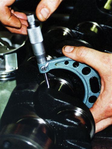 Crank main journals are checked for roundness with a micrometer. This process is also used to establish main bearing clearances.
To get better performance, this engine uses studs instead of main bolt caps. This eliminates main bearing cap "walk" and breakage and also utilizes the steel support straps. Stock caps will crack in high horsepower applications. The cap supports are installed on the front four main caps and are available as a kit from Esslinger.
When main bearing straps and studs are used, the stock main bearing cap must be milled flat on the bottom. Finished height from the parting face to the flat milled surface will range from 2.065 to 2.075 inches.
In order to contain the stamped steel fire ring of the head gasket, the 2300 block must be fitted with O-rings on top of the block surface. The fire ring can move because of excess pressure due to higher compression, better air flow, or higher rpm. O-rings should be installed just outside the gasket fire ring. They will nearly touch each other.
 Rod journals can be miked for roundness and wear. Again, it's a process that can establish bearing clearances.
Once the block is machined, an additional cleaning provides a better working platform. This cleaning involves a thorough spray with carburetor cleaner, followed by a wash with hot, soapy water. All oil passages and hard-to-reach places need to be cleaned. Rinse with a strong stream of water and dry with compressed air. Don't use a towel for drying because of lint residue. The block will need to be covered with a plastic bag to stay clean. New freeze plugs should be installed.
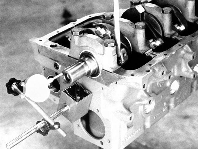
Before any work is done with the crankshaft, the piece should be magnafluxed. Also check to see if the crank is straight. Set it into the block with bearings in the main journals at the extreme ends of the block, and dial indicate the center main journal. There should be a variance under 0.0005 inch. The crank should be checked for wear, using a micrometer. Several readings should be taken across each journal to check for roundness. The numbers for each journal should be checked more than once and recorded.
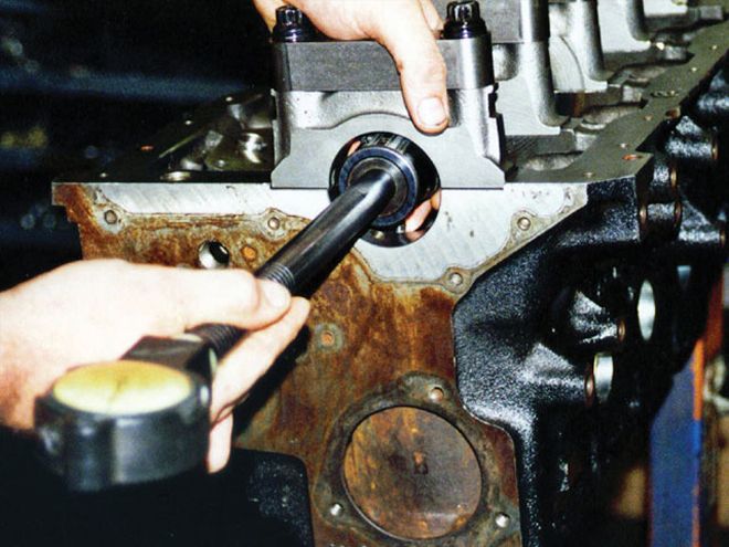
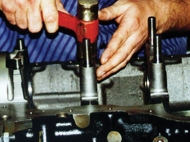 Main bearing caps should be installed with a brass hammer. This will help to get the caps fully seated and perfectly aligned.
Esslinger Engineering recommends that a stock crank be turned 0.0105 inch under on both the main journals and the rod journals. When the journals are turned this amount, use 0.010-inch undersize bearings. To relieve stress risers and improve oil flow to the bearings, all oil holes in the crank journals should be chamfered. After all of the machining processes are completed, the crank should be hardened for improved durability.
Main bearing sizes must be measured to determine clearance. Insert the main bearings in the block and torque down the caps. Use a dial bore gauge for the inside diameters and record the readings. To calculate clearance, subtract the crankshaft main journal size from the main bearing size. Main bearing clearance should be 0.002-0.0025 inch. Rod bearing clearance should be 0.0025-0.0030 inch.
To clean, always wipe off the bearings with lacquer thinner, front and back. Use lacquer thinner to clean the bore opening. Before installing the crank, apply assembly lube to the bearing surfaces.
 Use a quality dial bore gauge to measure the inside diameters of the bearings when determining bearing clearance.
The main bearing caps are installed in the same order they were removed. They are torqued to 90 ft-lb in three incremental steps. Follow the torquing pattern to get even clamping forces. Crankshaft endplay should be 0.004-0.008 inch on the big main journal block. On the small main journal block, the endplay should range between 0.007 and 0.012 inch. Endplay cannot be adjusted on this block.
To be sure this engine has plenty of strength for an 8,000-rpm grind, Crower Sportsman connecting rods were used. All rods were weighed to make sure they were within 2 grams of each other, and they were. The rods were magnafluxed and once they passed this test, a micrometer was used to check for roundness. It is important to be sure you are working with a matched set of rods. Measure between the top of the large bore and the bottom of the small bore. The variance of the four rods should not exceed 0.001 inch.
Properly reconditioned stock connecting rods can also be used. A 0.125-inch diameter oil hole must be drilled into the bottom of the small end of the rod on each side to provide additional oiling to the wristpin. Stock 2300 rods use a wristpin that is press fit into the small end, making assembly somewhat more difficult, and some power is lost in friction. To remedy the problem, bore the small end of the rod and insert a bushing so that full-floating wristpins can be used. The process must be done by a machinist.
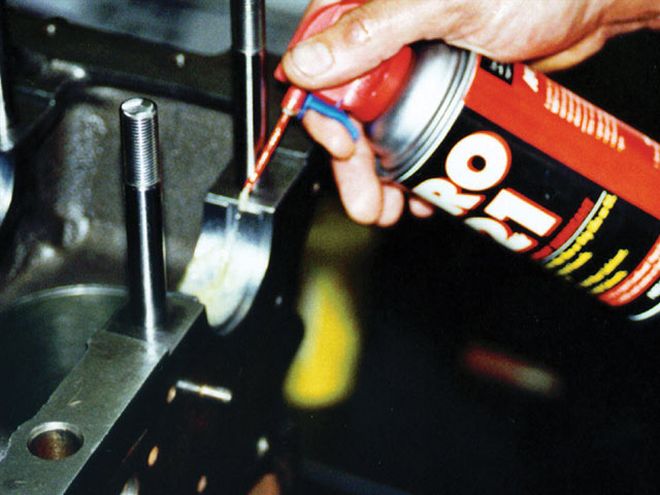 Apply assembly lube to the bearing surfaces before installing the crankshaft.
The rod beams are ground to remove any excess metal. The rods are polished to remove stress risers, forging lines, pits, and marks off the shank. The rods are shot-peened and balanced. Stock connecting rods should use high-quality ARP bolts. Stock bolts should never be used for racing.
To prevent damage to the crankshaft bearing races, slip rubber tubing over the rod bolts when installing the rods and pistons. The connecting rod bolts should be torqued to the manufacturer's specifications. In our case, the torque value was 50 ft-lb for the Crower rods. Before you begin torquing a rod bolt, check its length with a micrometer and write that number down. Torque to the manufacturer's recommendations in three steps. Then measure the bolt again for stretch. The stretch tolerance for Crower is 0.004-0.006 inch.
Be sure to check the rod side clearance. Forged or billet rods have a side clearance allowance of 0.010-0.015 inch. Once the pistons are installed, check the deck height for the desired compression ratio. Deck height is the distance the piston is down in the bore. With the 2.3L engine, this distance should be 0.0 inch.
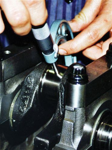
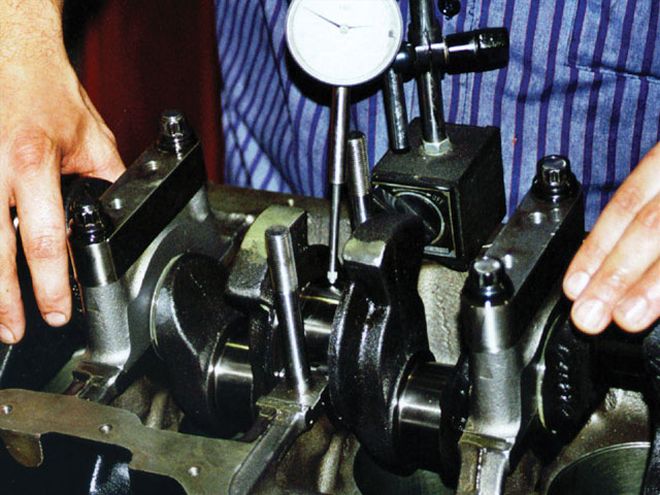 Before main studs are torqued, check the runout on the crank. Install a dial indicator against the center main journal of the crank and rotate the crank.
For this project, JE forged pistons were used. The piston is a flat-top design, preferable to a domed piston in this application. The radii on the valve reliefs were buffed to smooth the radii so hot spots would not occur. Each piston was weighed to determine if it was within 2 grams. Since we were using forged pistons, we also used Esslinger wristpins. They are manufactured from tool steel for high strength, but weigh much less than stock or replacement pins. Lighter weight means less wear and quicker acceleration. For better wear protection, a thin coating of assembly lube is placed on the wristpin during assembly.
Total Seal gapless rings are a popular choice for the 2300 engine. The second ring is a gapless design, which offers less blow-by and reduces horsepower loss, an important consideration for a small displacement engine. The Total Seal rings also tend to reduce oil temperature because of lower blow-by, and oil dilution is also reduced because of the rings' sealing qualities.
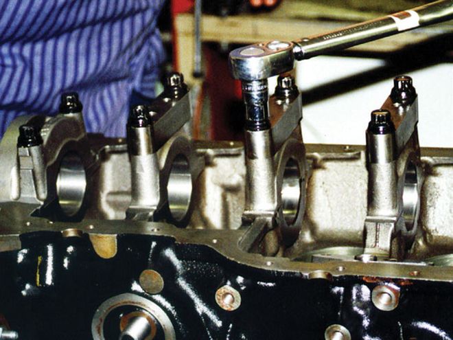
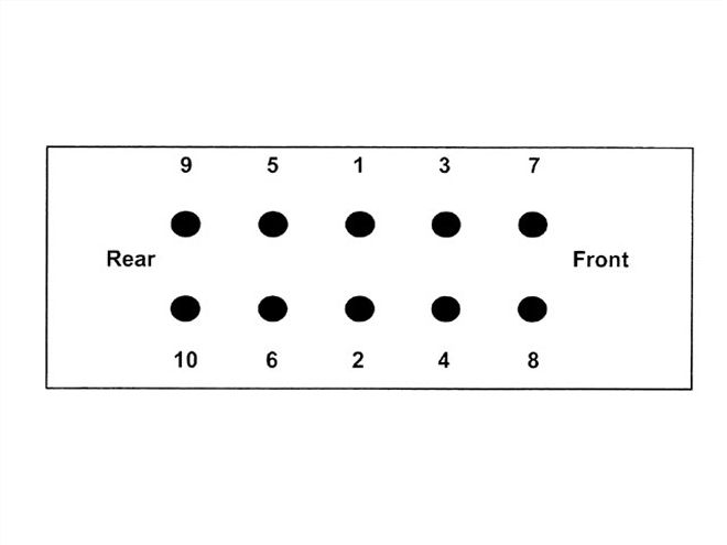 The main bearing caps must always be torqued in this order to get the clamping forces evenly applied to the block. Torquing is done in three steps: 30 ft-lb, 60 ft-lb, and 90 ft-lb.
With Total Seal rings, the red side of the top ring must be up when installed. If the top ring has a dot, the dot goes up. Unmarked beveled rings should be installed with the bevel side up. To use a gapless second ring, the machined ring is installed first, groove side down. The gap is placed 180 degrees from the gap in the top ring. Install the thin rail into the machined ring with the gap placed 180 degrees from the main ring gap. The oil control ring is installed with the expander first, with the gap 90 degrees from the open end of the wristpin. Install the upper rail with the gap 1 inch to the left of the expander gap and the bottom rail gap 1 inch to the right of the expander gap. End gaps should be 0.017 inch on all three rings. It is important that all four oil rings exert the same installed drag force on the cylinder walls. Insert each piston upside down into the cylinder bore with only the oil ring installed. Use a fish scale to pull the piston up through the cylinder. The installed drag force, shown on the fish scale, should be 15-19 pounds.
Do not oil the pistons or piston rings during installation. A light oil on the cylinder walls will allow the pistons to slide. Excess oiling of the rings will keep them from seating. The pistons and rings should be installed with a tapered ring compressor.
 Checking crankshaft endplay.
Several different heads have been used on the 2.3L engine, which are distinguished by their intake port shape and combustion chamber shape. D-port closed combustion chamber heads were used from 1984 to 1988. The D-port open combustion chamber head preceded it from 1981 to 1984. Oval port open combustion chambers were used from 1974 to 1981. For the Ranger head, a round port model was put into place. The open combustion chamber is shaped like a "D" while the closed combustion chamber is heart shaped. D-port heads offer the best flow characteristic. The D-port closed chamber head is best for stock classes that cannot modify their heads. An oil pressure restrictor should be inserted into the cylinder head at the left-rear corner in the oil gauge gallery on heads that use solid valve lash lifters.
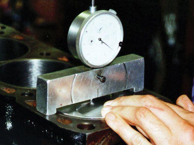 Deck height must be measured. Deck height is the distance the piston is down in the bore.
Uncracked 2.3 Ford heads are becoming hard to find, so Dan Esslinger of Esslinger Engineering designed a new aluminum D-port head that can serve as an affordable high-performance head and a stock replacement part. It is engineered to accept both hydraulic and solid lift components. As cast, it can flow as well as a fully ported iron head and weighs 30 pounds less. Intake ports flow 18 cfm higher, and exhaust ports were 17 cfm higher than Esslinger's best full-ported iron head. After establishing a baseline with the stock cast head, the aluminum D-port was installed. Above 6,000 rpm, horsepower climbed rapidly. A 12hp increase at 7,000 rpm was seen with this head. The gain reached over 20 hp at 7600 rpm.
Stock head preparation involves many necessary steps: 1) hot tanking to remove sludge and deposits; 2) magnafluxing the head for cracks; 3) cleaning the head in a Steela- brator shot machine to remove scale, rust, carbon, and gasket material; 4) washing with carburetor cleaner to remove steel dust; and 5) washing with water and spraying with WD-40 to prevent rust.
Here is the proper order for reworking the heads: 1) install new bronze valveguides; 2) do a valve job; 3) CC the combustion chambers; 4) mill the head; and 5) install solid lash adjusters.
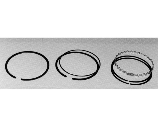 The Total Seal gapless second ring (middle) incorporates two overlapping rings, which eliminate the ring endgap. The gaps of the two rings are placed 180 degrees apart.
The stock valveguides are cast into the head, so a used head will likely have worn guides. The stock valveguide bosses are milled off. Old guides are drilled out to 0.50 inch. New silicone bronze valveguides are press fit with a drop of Loctite 271 for extra insurance. Spot-face the bottom of each guide in the cylinder to get them flush with the existing casting. Ream the inside diameter to 0.34475 inch. Use a finish reamer for the .001-0.0015-inch clearance for intake and exhaust valve stem clearance.
Stock diameter Esslinger stainless steel valves are used for the intake and exhaust (1.740-inch intake, 1.50-inch exhaust). The valves feature a single groove keeper design, different from the three-groove design for Ford. Valve seats are cut at 30, 45, and 60 degrees, starting with the 45 degree main seat, then proceeding to the 30 degree cut and the 60 degree top cut. The angle accuracy of the cutting stones should be checked before the process. After the valves are ground, they are hand-seated for seal. To check the seal, fill the combustion chamber with solvent and look for leaks.
The head must be cc'd to insure an even compression ratio. If the ratio is uneven, cylinders will not do an equal amount of work, reducing power and efficiency. Begin the cc process with the head fully assembled as it will be installed on the block. The head should be secured on a flat surface with the combustion chamber up. A chemist's burette and clear plastic plate are needed for the process. The plate must be at least 1/2 inch thick and large enough to cover and seal the chamber. Coat the head surface with a light film of grease to seal the plate, and press the plate over the chamber. The plate should have a hole large enough for the burette to discharge fluid. The best fluid to use is WD-40. When the burette is full, it will read 0 cc. As fluid is discharged into the chamber, read the graded markings when the chamber is full.
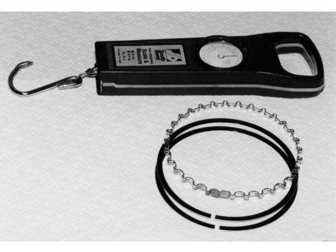 A fish scale can be used to measure the drag force of the rings on the cylinder walls.
You need to make sure that no fluid leaks and that all air bubbles are out of the fluid. An exact volume is not likely, but the chambers should be within 1/2 cc of each other. Lower volume chambers should be worked to conform to the highest volume. Remove metal from the chambers to equalize the cc measurement. Do not sink the valves into the head to equalize.
The head is milled to increase the compression ratio. With D-port heads and oval-port heads, the maximum that should be milled off is 0.150 inch, if the rocker rail-to-deck height is 3.800 inches (factory spec). Angle milling is not advised. Always cc the combustion chambers before milling the heads because you need the combustion number to determine compression ratio. Shorten the locator sleeves and head bolts after milling, and always clean out the bolt holes.
Torquing the head will require 85 ft-lb with bolts and 90 ft-lb with studs. These numbers are valid with motor oil applied to the threads. Follow the proper torque sequence and torque each stud in progressive steps. Run the engine for 20 to 30 minutes after initial assembly, and retorque the head after it has cooled. The proper head gasket is the Fel-Pro blue gasket (PN 8993 PTI).
Next month we'll continue the assembly process to get the engine ready to race.