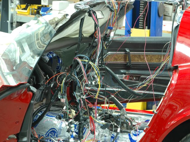
We’ve spent the last couple of months wiring Scarlett, our project 1972 Vette coupe, as we’ve worked to integrate the new factory harnesses from Zip with the FAST wiring harness for the XFI computer. In addition to routing the factory harnesses, we’ve corralled the extra engine wiring into a single, firewall-mounted circular connector and made the dash easy to service by combining the gauge wiring into a few small Molex connectors. While we’ve been focused mostly on the EFI wiring, we’ll also be adding other accessories that will require power, and we didn’t want to get it just by tapping into factory wires.
After adjourning to Waytek Wiring, our favorite source for OEM-grade electrical components, we ordered a busbar, a few fused distribution blocks, and weather-sealed Hella relays. Before we get into deep water, though, a few words on electrical theory are in order—please don’t stop reading, it’s not that painful. Electricity is like water: it has to go somewhere and it has to come back. “Going” is called positive, coming back is called ground. Electricity is generally measured in volts (following the water analogy, think “pressure”) and amps (think volume). The voltage is standardized in most cars at 12 volts, but the number of amps varies based on what the electricity is operating.
Even if more amps are available than a component needs, it will only use (“draw”) the current that’s necessary. If something fails, however, and the component draws more current than needed, the added amps can damage it. Fusing the current before it gets to a component gives the electricity something to break before it damages something expensive or causes a fire, so it’s wise to use appropriate fuses (which are rated in amps) before the electricity gets to anything it’s liable to damage.
In our case, we needed two types of power: 12 volts that’s constantly on and 12-volt switched power that only comes on with the car. We started by running the power to a fused distribution block inside the passenger-side fender vent, then through the firewall using a Delphi HES connector. Although the HES connector can take wires as large as 10-gauge, each pin is only rated at a max of 60 amps, so we put a fuse in place before the power gets to the connector to avoid cooking the connector. Once inside the car, we ran two heavy 10-gauge wires (one 12V constant, one switched) to a pair of fused distribution blocks where each individual accessory will be plugged in and a matching fuse installed. Each block is rated to a total of 100 amps, but since our connector can only take 60 amps per pin, we added up the different electrical loads to make sure we stayed well within that number.
We also ran a 10-gauge ground wire from a large stud in the fenderwell to a common ground (the busbar) that has several threaded studs on it. The stud in the fenderwell will be grounded to the engine, and we’ll run a second heavy ground wire from the busbar to the battery once it’s installed.
Under the hood, we used relays to avoid running an unnecessary amount of power through our wiring. A relay is basically a switch with four wires: a heavy amperage input wire, a similar output wire, and a trigger wire along with its ground. When the trigger wire is energized (generally by flipping a switch) the relay “turns on,” allowing the amperage coming into it to flow out the output wire. This keeps you from having to run the max power needed through the switch itself. Instead bringing a heavy current load into the car, through a switch behind the dash and back out of the car, a single wire from the switch on the dash can go to the engine compartment, where a relay is placed close to the power source such as an alternator.
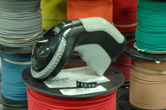
01. If you’re not taking notes and marking things as you go, you’re doing it wrong. We used a Dymo label maker to print labels for the major components, and color-coded with red label tape for constant-on 12-volt power, and black for switched.
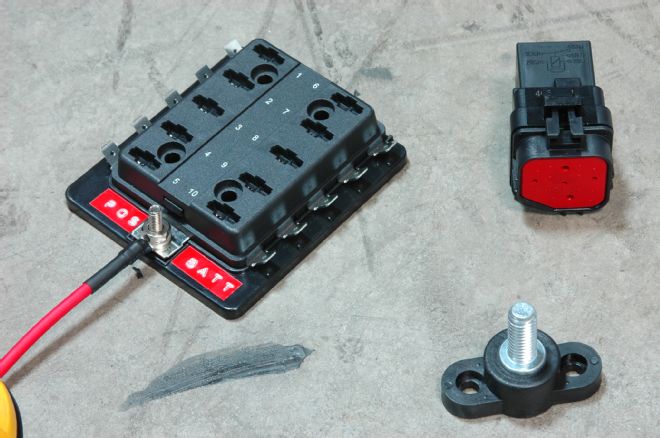
02. Three of the major components we used in providing for our additional power needs: a fused distribution block with one input and 10 outputs, a Hella weather-sealed relay, and a stud for a common ground. While the Hella is a five-pin relay, for this application we typically only used four of the contacts.
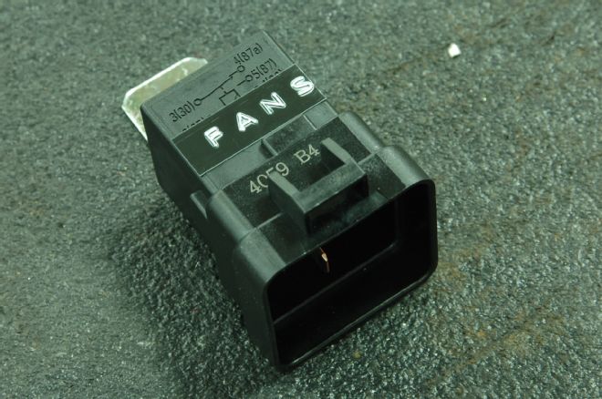
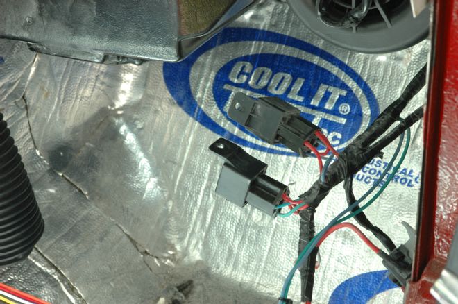
03. Part of what we started with, this add-on harness inside the car powers the fuel pump and the fans. Note the relays and in-line fuse holders. While there’s nothing wrong with either, we wanted to consolidate both our relays and fuses into as few places as possible to make the car easy to service. We also wanted to keep as much power outside of the passenger compartment as possible.
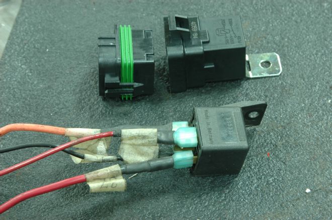
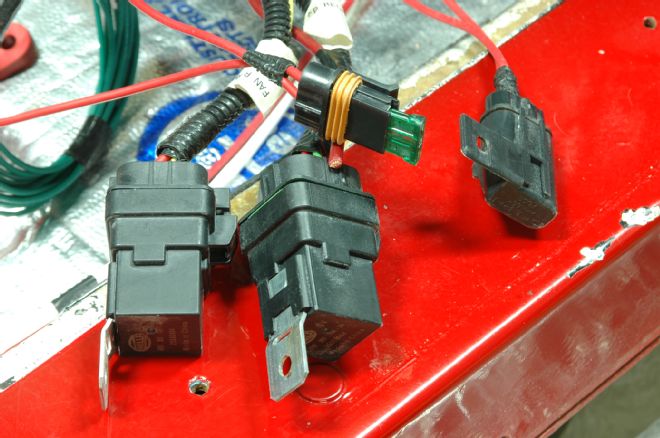
04. Here is a common aftermarket relay we used on an earlier project with Scarlett (bottom) shown with the Hella relay we used this time (top). Again, there’s nothing wrong with the earlier relay—it never failed us—but the relative exposure of the connections makes it much more likely to fail than the Hella version.
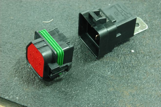
05. The weather-sealed Hella relay: wires pass through the red rubber wire dress at the bottom of the connector and plug upwards into the relay itself, where the two parts are sealed by the green skirt. Much better.
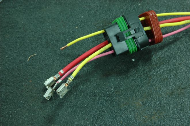
06. The Hella relay uses crimp-on terminals that are sized by the gauge of wire used. The wire is inserted through the rubber wire dress, through the housing of the connector, and then crimped. Once the terminal is in place, pull to seat it in the connector.
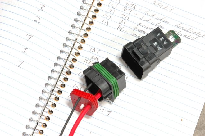
07. Once the terminals are seated in place, the wire dress can be pressed up into its receptacle in the connector. Since this is a five-pin relay and we’re only using four, we used a plastic plug to seal the unused hole in the wire dress. The fifth pin serves as an output for power when the relay is turned off, rather than on, a feature we’ll use later, but not here.
08. Again, label everything as you go—it’ll save hours of tedious multimeter work later as you try to figure out what powers what. While there are other things to be powered, we started with the fans and 12V switched power.
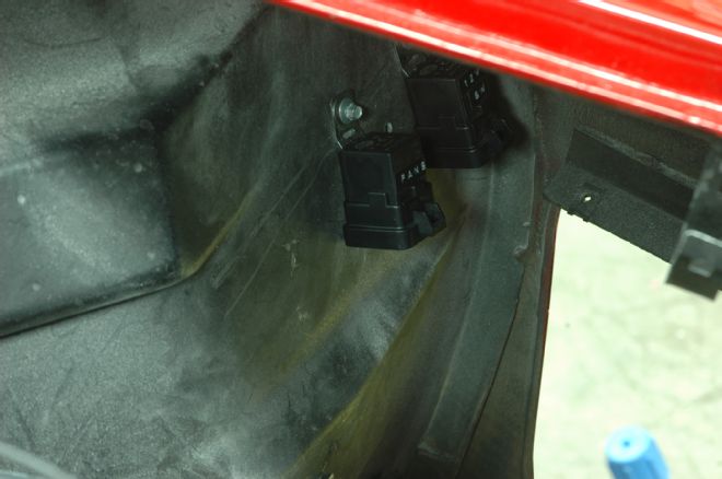
09. Since Scarlett is mercifully equipped with a removable fender vent—another reason to love the 1970-’72 Sharks—we mounted the relays in a row to the rear of the inner fender, up where they’ll have some protection from the weather but still be easy to reach.
10. The distribution block and common ground stud loosely screwed into place. The large stud will be connected to the engine block by a heavy 8-gauge wire and will serve as a common ground for the relays mounted above it, as well as for the ground wire going into the car.
11. Numbers-matching guys, look away. We had to get the power through the firewall somewhere, so we cut a hole in the firewall just under where the factory A/C was previously located and sized it for a Delphi HES connector similar to the one we used for engine wiring, but with fewer, larger contacts.
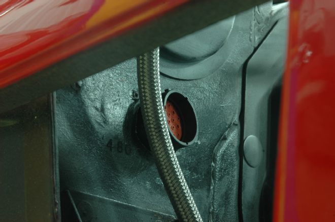
12. The connector is put in place on the firewall. While the engine connector has 47 pins, most of which are sized for 18-gauge wire, this one has 19 pins, 6 of which will accept wires up to 10-gauge, which gives us a good way to get heavy amperage through the firewall and to where we need it.
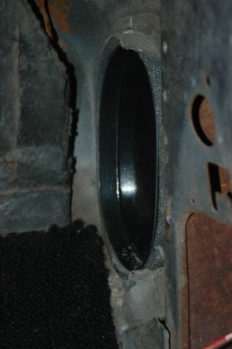
13. This block-off plate was installed in the kick panel area as part of our Vintage Air installation. It had to be removed (even if only temporarily) in order for us to route wiring through this hole and forward to the firewall where we mounted the HES plug.
14. One place we didn’t reinvent the wheel was the relays and circuit breaker for the Vintage Air system. Although we had to remove them in order to access the block-off panel in the previous frame, we’ll keep them mounted to the kick panel area. Since there are no fuses and the breaker will reset itself, there’s no need to have ready access to it.
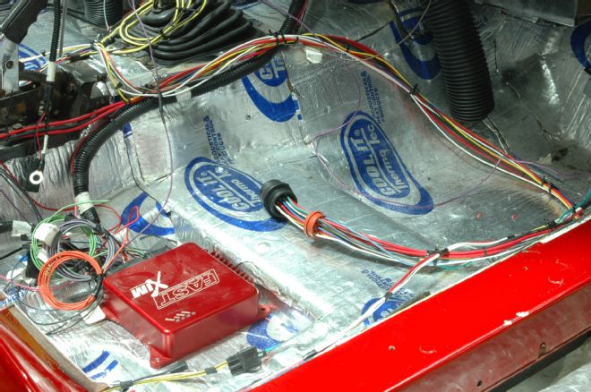
15. As with the EFI wiring, we zip-tied all of the wiring going through the firewall via the HES plug into a single snake-like bundle. For final assembly, we’ll separate the heavy 10-gauge wires from the smaller ones to reduce the chances of the heavy current affecting the signals transmitted by the smaller wires.
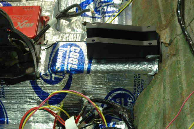
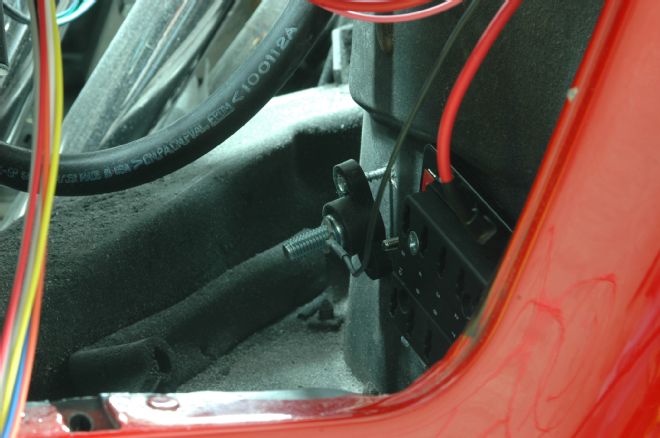
16. There’s not much room inside a Shark, so we looked to the parking brake housing area to mount the distribution blocks. While this steel reinforcement goes under the plastic housing, we’ll be cutting and re-welding it to make clearance for our distribution blocks.
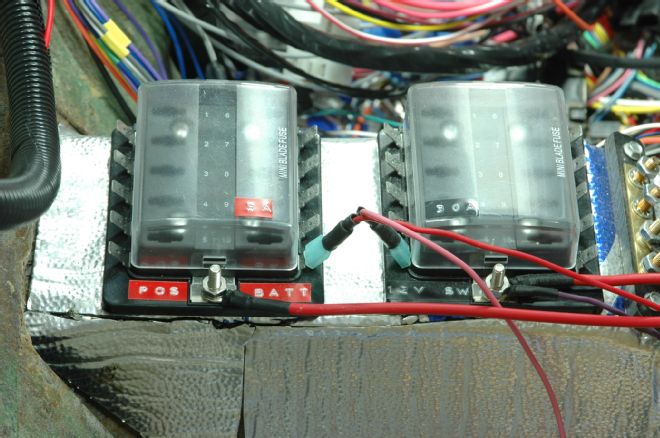
17. Our two fused distribution blocks screwed into place. This puts all of our power in one place, as well as all of our fuses, so when something stops working, or if we need power for a new accessory, it’s all in one place, and it’s relatively easy to access. The blocks have 10 fused outputs each and use the smaller mini blade-type fuses. We even splurged for the ones that light up when they blow. Note that even the covers are marked for how many amps each fuse should be, and that they’re color-coded to avoid putting the wrong cover on the wrong block.
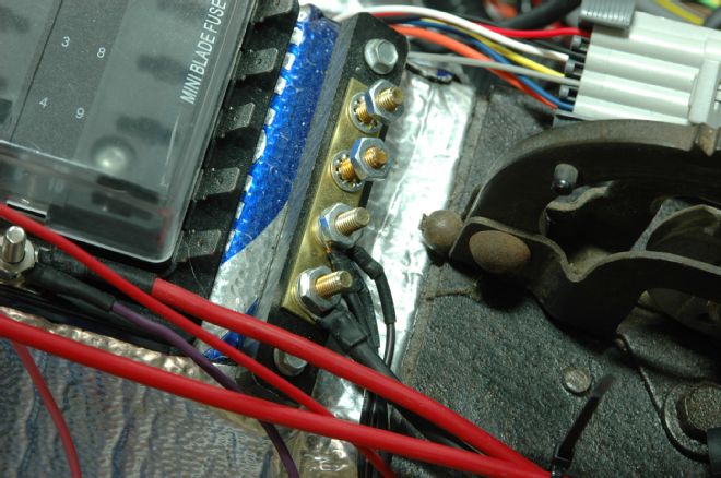
18. The busbar we used for a common ground was mounted to the area between the forward-most distribution block and the parking brake mechanism. We connected it to our ground stud in the front fenderwell via the HES connector and will add a second ground wire that goes to the battery once it’s installed. You can never have enough grounds.
Catch up on the previous installments of Project Scarlett!
1972 Chevrolet Corvette Scarlett Project Car - LS3 416 Installation
1972 Chevrolet Corvette Scarlett Project Car - Sidepipe Install
1972 Chevrolet Corvette Scarlett Project Car - Six-Speed Manual
1972 Chevrolet Corvette Scarlett Project Car - EFI Fuel System
1972 Chevrolet Corvette Scarlett Project Car - Cooling System and Hydroboost
1972 Corvette Scarlett Project Car - Vintage Air Gen 4 Underhood Components, Part 1
1972 Corvette Scarlett Project Car - Vintage Air Gen 4 Underhood Components, Part 2
1972 Corvette Scarlett Project Car - Replacing the Factory Wiring Harness
1972 Corvette Scarlett Project Car - Dash and Gauge Installation
1972 Corvette Scarlett Project Car - Dash Wiring Harness Installation
1972 Corvette Scarlett Project Car - Dash Prep and Radio Installation
1972 Corvette Scarlett Project Car - C3 Column Rebuild