
Performance is all about pushing the envelope. As camshafts become more aggressive in the search for more power, these lobes make life increasingly difficult for valvesprings. This may seem like a problem only for drag racers spinning stratospheric-rpm small-blocks, but this situation applies even to everyday street engines. Valve float and loss of valve control can happen even at conservative engine speeds.
Mass HysteriaThe valvespring's only job is to control the valve. This means that the valve should open and close only when the camshaft signals the valve to do so. Roller cams drastically increase acceleration rates, especially compared to flat-tappet lifters, which means that the valvespring must now control a mass that is now moving much quicker at the same rpm. That might seem like a simple thing, but keep in mind that the rocker-arm ratio also multiplies the acceleration rate of the valve. On the opening side of the lobe, the valve accelerates up to its greatest speed and then must start decelerating back to zero velocity at maximum valve lift. Then, the valve must begin to close, accelerating up to a given speed and then back to zero again as the valve closes. All of this has to happen very quickly, especially at high rpm.
All of this sounds fairly simple-and for stock engines, it is. But as we add variables like increased valvetrain weight and engine speed, the situation changes drastically. As engine speed increases, the valve must open and close in a shorter period of time. What is easily accomplished at 3,000 rpm must be completed in half the time at 6,000 rpm. At 6,000 rpm, an intake valve must open and close 50 times a second! Again, if the valvespring is designed, installed, and used properly, this is usually not a problem. But consider what happens when we add weight into this equation with a larger valve. Simple physics tells us that heavier objects require more force to accelerate, just like a heavier car requires more horsepower to accelerate. Adding larger valves means the valvespring must control additional weight, more than likely at higher engine speeds.
Here's the rub. Bump the valvespring pressure up to increase control, and that additional load pushes down on that little piston inside the hydraulic lifter. At higher engine speeds, the acceleration loads are so great that the lifter is no longer able to maintain the oil in the lifter cavity, pumping the lifter down. This creates excessive lash and lost valve lift that quickly kills power. So, there is a limit to the amount of valvespring pressure we can apply to control this heavy valvetrain. Of course, we could bolt in a new mechanical roller camshaft, but that's an expensive solution. Since we can't increase the spring load with a hydraulic lifter, the more elegant solution is to reduce valvetrain weight.
Weight WatchersRacing-engine builders have known for decades that lighter valvetrain components allow higher engine speeds without loss of valve control. The key is to reduce weight on the valve side of the rocker arm, because the rocker multiplies the lobe acceleration rate by the rocker ratio. This is the idea behind titanium retainers, valvesprings, and ultra-lightweight titanium valves. All of these are excellent ways to reduce the mass of the valvetrain that must be accelerated, but they are also very expensive, and for the most part, race-only solutions. But let us consider the valvespring itself.
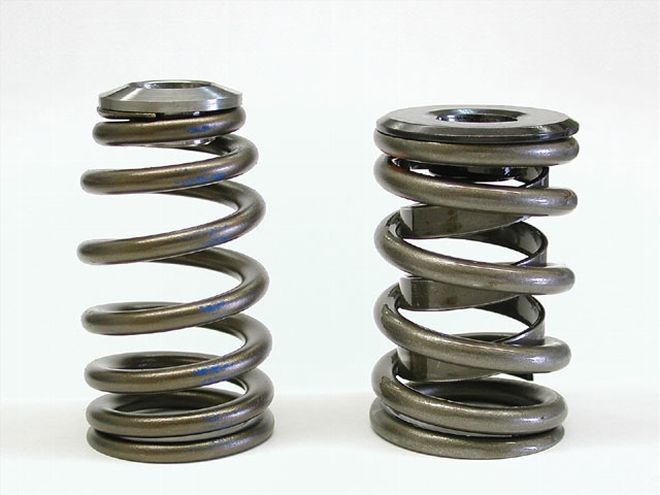
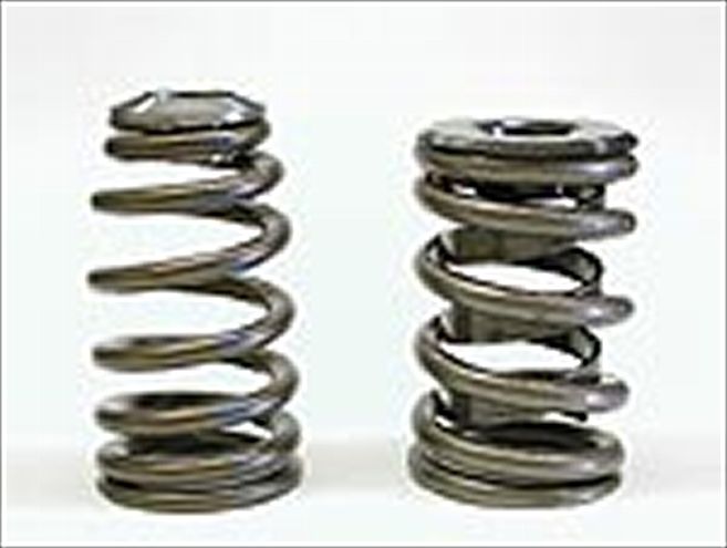
For several years, GM has employed a beehive-shaped spring in the LS1 engine. This spring's ovate or oval wire provides more lift without increasing the spring height. It also has a variable rate, meaning that when first compressed, the spring operates with a lower spring rate and progressively becomes stiffer as the smaller-diameter windings compress into the larger coils. Most importantly, the beehive shape reduces the weight of the spring. This is a critical point, because coil springs must use a certain amount of their pressure to control themselves. So, if we reduce the mass of the spring, more of the spring pressure should be available to maintain control of the valve, and it may be able to accommodate a higher engine speed. The beehive shape also uses a radically smaller and lighter retainer. This is important because we're reducing the mass at the top of the spring, which reduces lateral leverage as well. Keep in mind that the top of the spring travels much greater distances and is subjected to greater accelerative forces than the bottom of the spring.
Valve FloatBefore we go any further, it's important to define what we mean by loss of valve control. This is most often referred to as valve float because the common misconception is that the lifter launches itself off the nose of the cam. While this can and does occur, the more common result of a loss of valve control is when the valve bounces as it approaches the seat. Generally, this will happen to the intake valve first because of its greater weight. This results in a loss of engine power because cylinder pressure is pushed back into the intake manifold instead of remaining in the cylinder. The biggest problem is identifying when the power loss occurs, because it may happen a few hundred rpm earlier than what is considered normal for a given application.
Classic valve float is usually accompanied by a dramatic loss in power and an obvious misfire, but most engines are already suffering power loss from valve float before it becomes audibly noticeable. This is what happened to our big-block and why our engine picked up significant power at the top end of the curve.
Don't Freq OutMost springs are rated for a certain load at a given installed height. That load is the pressure imparted on the valve to control it. Historically, load has been the main factor in matching a spring to a valvetrain, but given all the variables of rocker ratios, valvetrain weight, pushrod deflection, and a couple of dozen other items that affect valve operation, it's easy to see that matching a spring to a cam lobe and valvetrain requires much more data than just a load rating. Much of this has to do with what is called a spring's natural frequency.
At a given rpm, any valvespring will hit a frequency where it will naturally vibrate or resonate like a tuning fork. When this happens, the spring loses much of its ability to maintain control over the valve. This is why most single-wire valvesprings come with a flat wire damper. This damper is designed specifically to dampen the spring's natural frequency, especially when the spring resonates at an rpm where the engine spends time. Dual or triple springs use the friction between the inner and outer springs to perform this damping action.
The beauty of the beehive spring is that its conical shape and variable rate creates numerous, yet less dramatic, natural frequencies, which makes it much less susceptible to a loss of control. There's much more to this concept that would take volumes to discuss (and frankly we don't pretend to understand all of it anyway), but it's enough to say that the beehive spring takes advantage of the physics of its design to give it much more control.
Beehive BuzzComp Cams now offers new valvesprings that take advantage of this conical-shape technology to complement our favorite engine. One of the engines we have always had difficulty controlling is a big-block Chevy outfitted with a set of hydraulic-roller lifters. This is due in large part to the weight of a typical big-block valvetrain, which uses large, heavy, 31/48-inch-diameter valve stems. We've experienced mild valve float as low as 5,500 rpm on a hydraulic-roller-cammed 454 H.O. engine.
To prove this point, we bolted up a GM Performance Parts 454 H.O. big-block to Ken Duttweiler's dyno and outfitted it with a Comp Cams Xtreme Energy 282 hydraulic-roller cam, along with a set of World Products Merlin Jenkins oval-port iron heads equipped with a set of Comp single-wire valvesprings (PN 911), which are the standard springs recommended for this cam. We outfitted the rest of the engine with an Edelbrock Performer RPM Air Gap intake, a 750-cfm Holley mechanical-secondary carb, and an MSD distributor sparked by a 6AL box.
Dyno man Ed Taylor performed the dyno test, equipping the Rat motor with the Comp 911 springs. At around 5,500 rpm, the engine went into serious valve float and would not rev past this point. Given the cam's duration and lift, it should have made power at least up to 5,700 rpm, but clearly the engine was limited by valve-control difficulties.
Comp then sent us a set of brand-new PN 29120 beehive springs designed specifically to address this valve-control problem on the Rat motor. As you can see by the accompanying spring-pressure chart, the beehive spring offers 30 pounds more load on the seat (part of this load is due to the shorter installed height), with open pressures within roughly 5 to 10 pounds. We installed these springs directly on the big-block heads with no prep work and with no other changes so we could do a direct comparative test.
Once the engine was back up to temperature, the first test with the new beehive Comp springs was a bit of a shock. We expected to see a slight increase in power above 5,000 rpm, but what we saw instead was a power increase virtually across the entire rpm band from 2,200 rpm to 5,700 rpm. There was only one point at 4,300 rpm where the power numbers were the same. Amazingly, we picked up 26 lb-ft at 2,400 rpm and then 20 hp at the top end at 5,600 rpm. The large gains also both occurred at the opposite ends of the rpm scale, with minimal changes in the middle.
We discussed this test with Comp Cam's spring design engineer Thomas Griffin, and he attributed the increase at low speeds to the additional load pumping the lifter down slightly, which could shorten the cam's duration and boost torque. To test that theory, we installed a set of Comp Cams mechanical-roller lifters and different pushrods to eliminate the hydraulic lifter as a variable. This is not a recommended procedure, but with a very tight 0.004-inch lash for a quick test, Comp felt we could get away with it. This test revealed 11 lb-ft less torque at 2,400 rpm than with the beehive springs and hydraulic lifters. This was at the 432 lb-ft that was the same exact rpm where we had gained as much as 26 lb-ft. This tells us that Griffin's theory was worth at least 11 lb-ft of the total 26 lb-ft change. However, this still leaves at least 15 lb-ft not accounted for.
ConclusionThis one test should by no means create the illusion that this new beehive spring is the ultimate solution to everyone's valvespring problems. Load is certainly still important to control valves at virtually any rpm, but it's also clear from Comp's dynamic testing and our own quick dyno flog that adding in the concept of valvespring frequency and what the entire valvetrain needs to ultimately control the valve is also very important. We've also learned that the lifter side of the valvetrain will benefit greatly from additional stiffness, especially for pushrods (even at the expense of additional weight), while the valve side of the rocker arm will work better by reducing weight. This makes life much easier on the valvespring.
You can expect to see more of this kind of information in the future as valvetrain testing and experimentation continues, but don't be surprised if you begin to see valvespring pressures become more conservative, especially with the use of these new beehive type of spring designs. Are you prepared to become a cone head?
Spring Specs Spring Free Outside Seat Open Coil Weight Length Dia. Load Load Bind Spring Ret. Locks 911-16 2.34 1.525 130 @ 340 @ 1.200 117 33 7 Single wire
w/damper 1.900 1.350 26120 2.50 160 @ 355 @ 1.085 98 7 7 Beehive
spring 1.850 1.300
We compared the top half weight of each spring plus the weight of the retainer to illustrate the additional mass of the normal valvespring versus the beehive spring. We added the weight of the retainer to half the weight of each spring. This really isn't fair to the beehive (the weight would actually be less because the top half of the spring would be lighter), but the difference between the two systems is still significant:
1 1/4 wt. 911 spring + retainer + locks = 99 grams1 1/4 wt. beehive + retainer + locks = 63 grams
This is a 57 percent increase in mass that the standard spring must manage compared to the beehive spring.
Cam SpecsWe equipped the 454 H.O. Rat motor used for our test mule with a Comp Cams Xtreme Energy hydraulic-roller camshaft (PN XR-282HR) using factory hydraulic-roller tappets.
Advertised Duration Lobe Separation Duration (@ 0.050) Lift Angle Intake 282° 230° 0.510 in. 110° Exhaust 288° 236° 0.510 in.
Parts ListAll part numbers listed here are Comp Cams pieces. The PN 26918 beehive spring is also a great drop-in for use with the small-block Chevy iron Vortec heads.
Component PN Beehive spring, big-block 26120 Beehive spring, LS1, LS6 26918 Beehive spring, LS1, LS6 26915 Beehive springs, 4.6L Ford two-valve 26113 Retainer, steel for PN 26120 795 Retainer, titanium for PN 26120 794 Retainer, steel for PN 26918 774 or 783 Retainer, titanium for PN 26918 772
Test Results Test 1 Test 2 Difference RPM TQ HP TQ HP TQ HP 2,200 416 174 433 182 17 8 2,400 421 192 447 204 26 12 2,600 449 222 462 229 13 7 2,800 466 248 474 252 8 4 3,000 468 267 479 273 11 6 3,200 480 293 497 303 17 10 3,400 501 325 515 334 14 9 3,600 516 354 526 360 10 6 3,800 520 376 529 383 9 7 4,000 523 398 527 402 4 4 4,200 516 413 518 414 2 1 4,400 504 422 505 423 1 1 4,600 490 429 494 432 4 3 4,800 478 437 485 443 8 6 5,000 468 445 475 452 7 7 5,200 454 449 463 458 9 9 5,400 433 445 442 455 9 10 5,600 412 439 430 459 18 20 5,800 - - 413 456 - - AVG 473.0 351.5 479.7 363.8 10.4 7.2