Nothing determines the "personality" of an engine more than the camshaft. Think of the cam as a mechanical computer, calling the shots on when and how the valves open and close. That computer is “programmed” by the grind imparted on it when the cam is manufactured, and it communicates that knowledge to the valvetrain with every cycle of the combustion process. To describe the characteristics of a cam lobe, we have specifications, namely lift and duration. The further specifications of lobe separation angle, overlap, and installed centerline angle provide more information on the cam’s design. Trying to select a camshaft without understanding these specifications is a blind shot at best. We don’t have the space here to delve into remedial cam card reading, but we fully explain each of these specifications in an accompanying piece (keyword search: "camshaft basics") at www.PopularHotRodding.com.
Assuming you know your basic camshaft specs, the very first decision to be made when contemplating cam selection is the actual type of cam to use. Here we have four basic choices: solid roller, hydraulic roller, solid flat tappet, and hydraulic flat tappet. Each has its advantages and disadvantages, but there is a great deal of crossover in their appropriate applications. Making an informed decision on what type of cam is right for you requires knowing the differences in their characteristics.
Hydraulic vs. Solid
Mechanically, hydraulic cams feature a lifter with an adjustment mechanism that will self-adjust to a zero lash setting. The upshot here is that valvetrain adjustment becomes an automatic function, while providing for quiet operation. In contrast, a solid-lifter cam requires a small amount of mechanical clearance in the system, provided by the valve lash. The lash must be checked periodically and adjusted as required to maintain the required clearance. Since the lash is a clearance, there is a greater amount of noise transmitted from the valvetrain. The amount of noise varies from almost indiscernible, to fairly intense, depending upon the amount of lash and the design of the lash take-up portion of the cam profile. For some enthusiasts, the sound generated by a solid cam is actually part of the appeal.
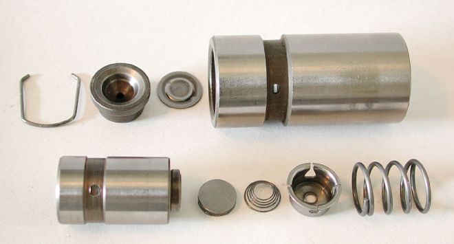 A hydraulic lifter, whether a flat tappet or roller, uses an internal hydraulic mechanism to automatically remove all of the clearance from the valvetrain, resulting in zero lash. The upside is low maintenance and quiet operation, but instability or the hydraulic circuit can limit high-rpm power.
At what rpm point can we expect the practical potential of a hydraulic to be a limiting factor? That answer depends on a wide range of variables. The major factors at play here start with the cam lobe design, and include the spring load, valvetrain stability and inertia, the stability and load of the springs, and valvetrain weight, including the springs and valves. If instability is generated anywhere in the system from the cam to the valve, the hydraulic mechanism in the lifter will begin to lose control. The rpm point at which these problems begin to occur varies widely based on these factors. A Gen III Hemi engine, for instance, with a good smooth cam profile can run with stability on a factory hydraulic roller lifter to 7,200 rpm, with the stock valvetrain. We have seen stock-style big-block Chevys with heavy ⅜-inch stem valves fall flat due to lifter instability at under 5,500 rpm with hydraulic roller setups. The situation with hydraulic flat tappets follows a similar pattern.
Solid-lifter cams lack the hydraulic circuitry in the lifters, providing a solid, mechanical link from the cam to the valve. Without the hydraulic system, a solid eliminates the potential for high-rpm valvetrain instability originating at the lifter. This makes a solid lifter better suited for high-rpm performance. So, is a solid cam a guarantee of rpm capability? Only if the rest of the valvetrain, particularly the valvesprings, allows the engine to reach its ultimate rpm potential. Solids are the only way to go in applications running very high rpm.
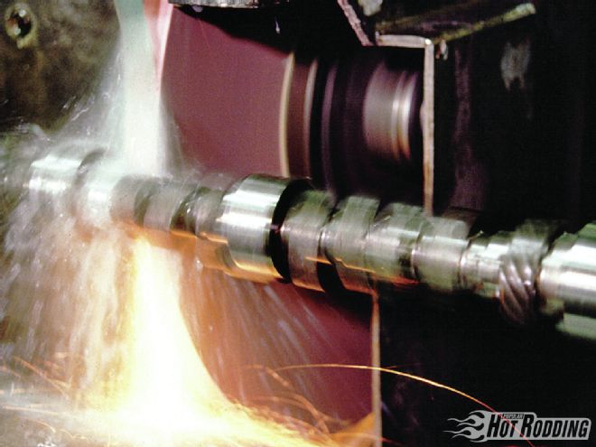
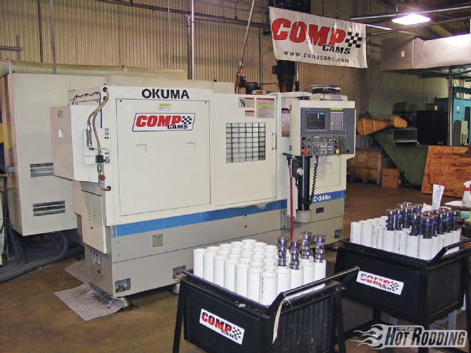 CNC cam manufacturing has found a place beside traditional grinding. The CNC is capable of unique profiles not possible with grinding, while allowing rapid prototyping and small-run manufacturing without the necessity of creating a lobe master.
To put a benchmark on the general rpm breakdown for solid versus hydraulic applications, a typical hydraulic should be very functional to 6,000 rpm with moderate preparation. Solids are generally the way to go if the peak rpm is in the 7,000-plus rpm range, while the 6,000- to 7,000-rpm range can be considered the crossover. Hydraulic lifter performance and rpm potential can be increased with a well-developed valvetrain and lightweight components, and the use of limited-travel hydraulic lifters.
Flat Tappet Vs. Roller
There was a time when roller cams were strictly the domain of race engines, in the form of early solid-roller arrangements. Compared to a flat tappet, which is limited in terms of opening velocity by the lifter diameter, a roller cam allows a higher opening velocity for faster valve action and more lift for a given duration. This adds up to a distinct power advantage. The roller design also benefits from the ability to handle much higher valvespring loads, which goes hand in hand with fast valve action and high rpm. With a flat tappet in a high-performance application, the limitation on spring pressure is the loading of the interface between the cam and lifter. The engine builder has to carefully balance the required spring loads against the potential for increased wear and even outright component failure. With a flat tappet, there is always a trade-off in camshaft longevity as the valvespring tension is increased, while aggressive lobe designs and high rpm demand high spring loads to maintain valvetrain control.
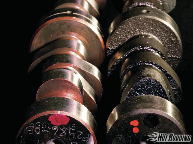
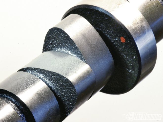 A roller cam lobe has a much broader appearance, but this is generally because of the geometry of how the roller lifter follows the lobe profile. The benefit of the roller is in higher spring capacity, and the potentially higher velocity compared to a flat tappet.
As with any hydraulic, the rpm potential is the limiting factor with a hydraulic roller. Once instability in the valvetrain causes the hydraulic mechanism to lose control, power production is over, however, with good parts in the valvetrain, lightweight components, and the appropriate valvesprings, the rpm potential should be enough to meet the needs of most street applications. Add the new breed of limited-travel hydraulic roller lifters such as those from COMP, and the rpm potential can be well into solid-roller territory. For a street application, a hydraulic roller has every characteristic to recommend it, from performance to longevity. The only real drawback of a hydraulic roller is the cost, which is substantially higher than a flat-tappet cam, especially in retrofit applications.
We talked to several professional engine builders including Engine Masters Challenge champions Jon Kaase and Tony Bischoff, both of whom greatly prefer roller cams for their customers’ engines. As Bischoff says, “For a street engine, I try to emphasize the benefits of a hydraulic roller in durability and reliability as top factors over a flat tappet, and the bonus is we can make more power. I will not build a flat-tappet engine unless the customer really insists.”
The lobe separation angle is simply the phasing of the intake and exhaust lobes for a given cylinder. The specification is the direct angular measurement between the peak lift points of the intake and exhaust lobes.
The solid-roller arrangement allows very high spring loads and very quick action at the valves, making it the best choice for all-out race applications. While ideal for racing, long-term high-mileage use is not a strong point of a solid roller. The common problem here is bearing failure in the lifters, with often disastrous consequences. As Chris Mays at COMP Cams says, “You can run a solid roller on the street, but it takes a certain kind of enthusiast, someone who is willing to perform routine inspection and maintenance. The newest direct oiling lifters help in this regard, but this isn’t the cam for someone who would rather not pull a valve cover once the engine is built.” Enthusiasts looking for the ultimate in horsepower and rpm may opt for the solid roller in a street application, but it comes with a trade-off in longevity. As Rod at Isky Cams tells us: "I don’t recommend a solid roller until it is more of a weekend toy or a bracket racer or race car. You can get them to last, but it costs quite a bit to get it set up properly. For guys on budgets, it is sometimes not cost effective."
Street vs. Race
In a race application, the goals of cam selection are very clear cut: Make the most power possible within the engine’s operating rpm range, within the constraints of budget, and acceptable maintenance and longevity. Typically, the budget here will steer the selection of cam type, with a large-journal billet solid roller being the ultimate piece, but only if substantial finances make it possible. Most often in the non-pro ranks of racing, the cam selection and the entire engine combination is a compromise based on the resources available. To make the most of any combination, however, selecting the optimal cam becomes a critical factor. Most engine builders will select the camshaft specifications based on previous experience, and trial and error in testing on the dyno and racetrack. In a race application, factors such as idle quality, vacuum, and low-end torque below the effective operating range take a back seat to horsepower.
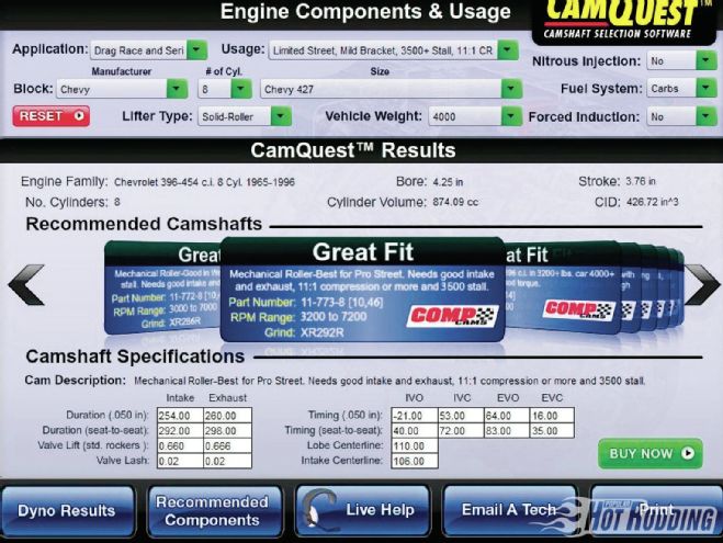 COMP Cams’ online CamQuest is just one program that allows the user to input his engine parameters and get multiple cam profile recommendations—in this case from the COMP cams catalog.
So, how would one select a cam within the above constraints to maximize engine power? Frankly, with all of the variables involved, the best resource these days are engine simulation programs such as COMP Cams’ CamQuest program, which will allow inputting detailed engine specifications and the user to juggle cam specifications while studying the projected results. Outside of years of experience, these programs are the best aid available to the DIY engine builder. Nonetheless, experienced engine builders will often just make a judgment call, mentally factoring in the targeted rpm range, head flow, compression ratio, induction system, and then draw on experience to make the call on cam specs, within the cam type dictated by the budget of the effort.
In a street application, cam selection becomes more complicated, as the end user’s goals and expectations cloud the process with dramatically varying goals. To begin with, the definition of a “street” cam is as individual as the guy behind the wheel. For some, the chop of a radical lope is the ultimate prize, while to others a powerful but smooth-running combination embodies the definitive street cam. Some are happy to pull the lifters of a solid roller each 5,000 miles for inspection in the course of routine maintenance, while others expect 100,000 miles without pulling a valve cover. Between these polar opposite objectives, you’ll find enthusiasts at every level of the spectrum. Even with the same engine combination, each will have their own definition of the ultimate cam.
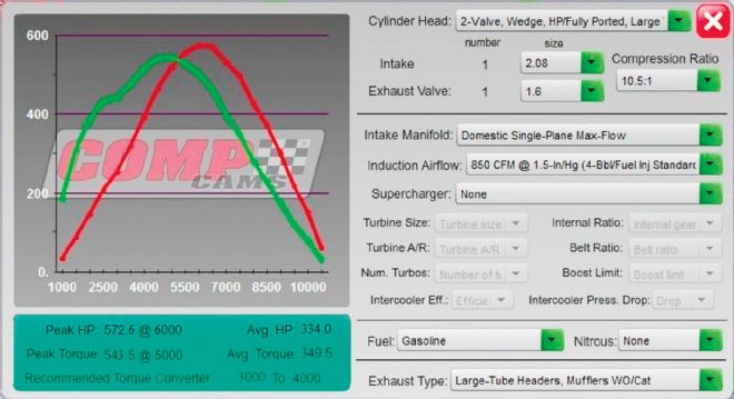 The free CamQuest program will even perform a dyno simulation for individual cams, allowing users to compare the calculated power curves between cams. This example is a rough simulation of the Dart 427ci SHP engine currently under construction in this issue, and uses a cam profile similar to the custom one we’ve chosen.
Multivalve Heads
Traditionally, we have been exclusively dealing with two-valve pushrod engines for decades; however, this is changing. With Ford leading the pack, first with the Cobra four-valve and now the new Coyote 5.0 liter, we are certain that multivalve engines will establish a bigger presence in the future. For some insight in cam considerations in multivalve engines, we spoke to engine builder Kenny Duttweiler. “On the four-valve twin-cam heads, the interesting thing is how much smaller the cam is to do the same job,” Duttweiler says. “To get a certain amount of horsepower per cubic inch, the camshafts will generally be 20-30 degrees smaller.
 Modern cams are typically ground with much faster rates of lift than traditional older grinds. The quick valve action improves torque and power, and the increased lift complements high-flowing cylinder heads. The selection of complementary valvetrain components becomes more critical, however, to maintain stability and longevity.
“Depending upon the design of the head,” Duttweiler adds, “you are often limited on lift, but in lift you’ll find it does not need anything as aggressive as a pushrod engine. If you look at the area of the intake valve compared to the bore as contrasted to a two-valve, there is quite a bit more breathing area. You step up the duration as the rpm increases; for example, we built a Toyota 4.5L engine destroked to 3.5 liters, and the cams were 262 degrees at .050, and it made peak power at 10,200 rpm—and put out 1,800 hp. That is about the biggest we have run; the big ones are usually 250 to 255 degrees at .050, and you’ll often be in the 230-at-.050 range with less radical combinations.” Kaase’s observations seemed to agree. “In the race engines with the four-valve, in general, it seems they need about 20 degrees less camshaft,” he says. “The heads flow substantially more, especially at the lower lifts.”
EFI vs. Carb
There are considerations that are particular to EFI applications when selecting a cam, especially if modifying an existing EFI-equipped car with a factory engine management system. Chase Knight from Crane Cams says: “A lot depends upon whether the ECU is going to be reprogrammed or replaced. These things are generally very vacuum sensitive. It is important to know whether the system will have the tunability to make the camshaft work with the control system. It also depends upon what the individual is interested in. If there is a concern about idle quality, then it will require a wider lobe separation or shorter duration to achieve better idle vacuum.”
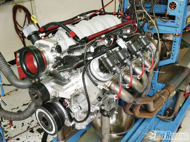 EFI cam requirements can vary from those of a carbureted application, especially if the engine management system offers limited tuning potential. The long-runner intakes characteristic of some of these engines also affects the optimal cam specifications.
Of course, the requirements will vary as you transition from a modified OEM application to a hot street or race setup with an aftermarket stand-alone engine management system. Jeff Says from Lunati tells us: “With an OEM-type throttle-body injection system, they can be untunable with long-duration, high-overlap cams. As you grow into full race EFI systems, the injection becomes irrelevant as far as the camshaft, because you can tune it around anything.”
A key factor that is often overlooked is the intake manifold configuration. Long-runner OEM-style intakes such as the LS engine pieces promote strong midrange torque. These manifolds tend to respond to a slightly wider lobe separation angle in comparison to a conventional four-barrel intake manifold.
Special Considerations: Turbos, Blowers, Nitrous
Power adders will alter the cam requirements, sometimes in similar ways. All three of these power adders will force in a larger intake charge, creating the potential for a large power increase. Duttweiler relates his experience: “I deal with both blowers and turbos and, believe it or not, there are real similarities. In particular, you don’t need as much duration, or as aggressive a lobe profile, or as much valve lift. Generally speaking, you are oftentimes going to run 20-30 degrees less duration than with a normally aspirated engine of a comparable rpm range. When you look at the range of durations we run on turbo camshafts, it is almost like the camshaft isn’t the main player. You have so many other things going for you with good cylinder heads and the pressurization on the intake tract; that takes care of the cylinder fill. Obviously, if you want to fill the engine with more air, you need to do it for a longer period of time, so you need a bigger camshaft.
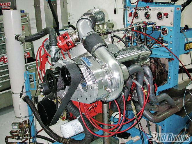 Blowers, turbos, and nitrous can have a dramatic affect on the required camshaft. Generally, all three favor a wider lobe separation angle than a naturally aspirated engine.
“In the lower power stuff, under 1,000 hp, you can be fairly mild with the camshaft and do a really good job. If you want to make, say, 2,500 hp with a small-block or 3,000 with a big-block, you have to cam it accordingly. On the big horsepower stuff you stay in the area of 270-280 at .050, while from 1,500-1,000 hp you’re going to be in the 250-260 range at .050. If you are in the 700-900hp range, those cams should be in the 220-240 at .050, depending upon the cylinder head. We run the lobe separation closer on the blower motors than we do on the turbo motors. You are not dealing with the backpressure with a beltdriven blower, you are just blowing it out the pipe.
“With turbos you are going to find backpressure, and when you are on the overlap cycle at higher boost levels, you are going to get an EGR effect in the intake runner. It will be a brief one, but it will be counterproductive to power production. So, the turbo engine will have a wider lobe separation. Say a typical big-cam normally aspirated engine will have a lobe separation of 112-113 degrees, while on the turbocharged engine it’s probably going to be 116-118 degrees of lobe separation. At the same time it will be a smaller camshaft in duration, so the overlap period will be substantially less. I prefer an earlier opening on the exhaust valve to get the valve far enough off the seat when the piston is moving up. With the turbo you are pushing a lot more exhaust out. Effectively you are doubling the displacement at 15 psi of boost, so you need to get a head start on the exhaust valve to simply blow down the cylinder sooner.
“Nitrous also has an effect on the cam timing for best power. Generally, the challenge here is providing for effective exhaust scavenging with the additional mixture burnt with nitrous. We typically see wider lobe separation angles in conjunction with longer exhaust duration. The cam phasing can be critical with nitrous, with more advance initiating the exhaust opening sooner to help blow-down the cylinder.”
Lobe Technology
One of the trends that is clear from the evolution of the performance cam is the move toward faster action, with more lift for a given amount of duration. The faster the valves are opened, the more torque the engine will generally make within a given rpm range. As Mays from COMP tells us: “The surrounding parts around the camshaft have just gotten so much better that it allows us to use much quicker-acting camshafts. You see the OEMs doing the same thing.” Things like better springs, more rigid valvetrain components, and lighter parts, especially in the valves, springs, and retainers, make the difference. Many of the cam lobes offered today deliver lift in the range of race cams of old, and do it within a duration window that would have been unheard of back in the day. By allowing more lift, these modern cams make more torque over a broader operating range, and they work hand in hand with modern high-flowing cylinder heads to tap into the high-lift flow.
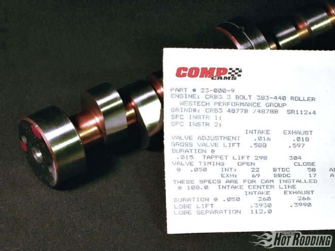 Knowing how to interpret cam specs and how they interact to affect engine performance is one of the key skills in cam selection. Aftermarket cams come with a cam card listing all the vital specifications.
Says from Lunati points out: “You always hear the word aggressive used to describe these fast lobe profiles. What that means is you can make a broader torque curve without giving up any power by shortening the seat duration and increasing the area under the lift curve by increasing the duration at higher lifts. As the acceleration rate increases, however, it can increase wear, and it becomes more difficult to keep the system stable. The lighter the components the better, especially in the retainers, locks, and valves. The weight of the lifter itself is less critical, while with pushrods, strength and stiffness are the more important factors.”
The Combination Counts
An engine is an assembly of interrelated parts, and just how these parts work together means everything to the power output. Cam selection will follow the engine combination. Jon Kaase brought home the point by comparing the effects of changes in the cam and heads in relation to power output: “If the engine doesn’t have very good heads on it and you put quite a bit of cam in it, it still will not make a whole lot of power, it will just run poorly down low. These two parts complement each other. Take for example a big-block Ford with a big cam, but it has a set of stock cast-iron 460 Ford heads. If you swap to our P51 heads, then it might pick up 100-200 hp. If you do it the other way around and have a really mild cam and add the set of heads, you might just pick up 20-30 hp. Then, you change the cam and pick up 100 hp. If you have a lot of cam in it and a stock head, the cam doesn’t help very much, but if you have no cam in it and change the heads, the good set of heads don’t do as much as they might. They pretty much have to go together.”
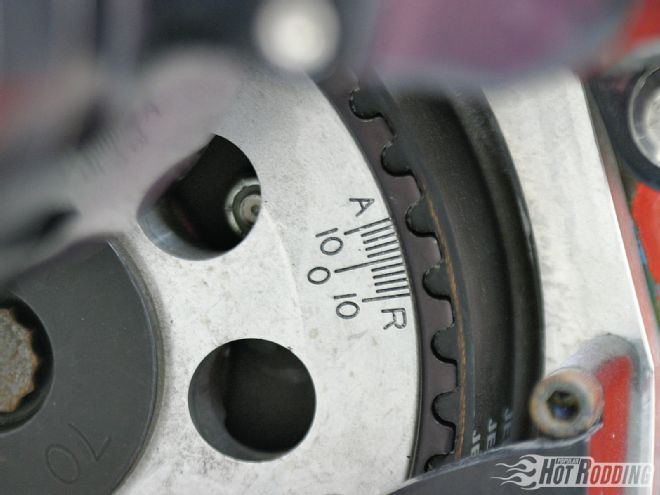 The cam must be properly phased to the crankshaft when it is installed. The position of the cam is given as the installed centerline angle. This measurement is given in degrees of crank rotation at which peak lift is achieved.
The right cam doesn’t just stop at the engine, it also depends upon what the user’s goals are. Mays from COMP relates: "I might have a guy with a 6-71 blown small-block rear-engine dragster doing nostalgia racing, or I might have exactly the same engine configuration, but the guy runs a Willys coupe street car, and he just wants it to sound good and drive it. You can’t cam those two applications the same, even if the motors are identical."
More Online!
Go to www.popularhotrodding.com to read a comprehensive glossary of camshaft terms, keyword search: "camshaft basics."