There are few things more important than safety and security when it comes to building a classic truck. Sure beauty and reliability are up there, but as the saying goes, chrome won't get you home. Oftentimes, some of the simplest safety devices get left out when wrapping up a truck build. I know I'm just as guilty as anyone else when it comes to leaving out certain things and a proper emergency brake is one of those items that I've left out of a handful of builds for various reasons; namely due to frustrations from trying to mate a stock emergency brake lever mechanism with a non-stock rear brake application.
My 1968 Chevy C10 is a great example. When I finished building it the first time around, I ended up with Ford drum brakes that needed to be mated up to the stock, underdash e-brake lever. What I found was that the e-brake handle needed to be pulled farther than the rear brakes would allow before the original detents on the handle mechanism would engage. Thus, no e-brake. Without a simple way of adjusting the amount of pull at either end, I picked up a $4 rubber tire chock and tossed it under the seat; problem solved.
Not having an e-brake, however, is something that's always bugged me and I promised myself that while I was under the C10 again, I'd sort it out for good. This time, I had a better solution than a simple cable mechanism and one that brought with it a few benefits as well; enter the E-Stopp push-button emergency brake system.
The E-Stopp is designed to replace an existing e-brake lever with a microcomputer-controlled, push-button system. A simple push of the button and the E-Stopp engages or disengages the e-brake, giving the user a visible cue in the form of a blinking LED button as well as an audible recognition signal until the process is completed. Once engaged, the button's LED remains lit (drawing 16 microamps) until the button is pressed again and the e-brake is disengaged, whereas the LED extinguishes.
The mechanical process of setting the e-brake is handled by a worm-drive actuator housed in a rugged aluminum case with about 3 inches of travel. A microcomputer control box relays the signal from the button to the actuator, which pulls the e-brake cable until it detects 600 pounds of resistance, whereupon it stops and locks in place. Once activated, the unit locks onto itself, drawing nothing from the battery to remain set.
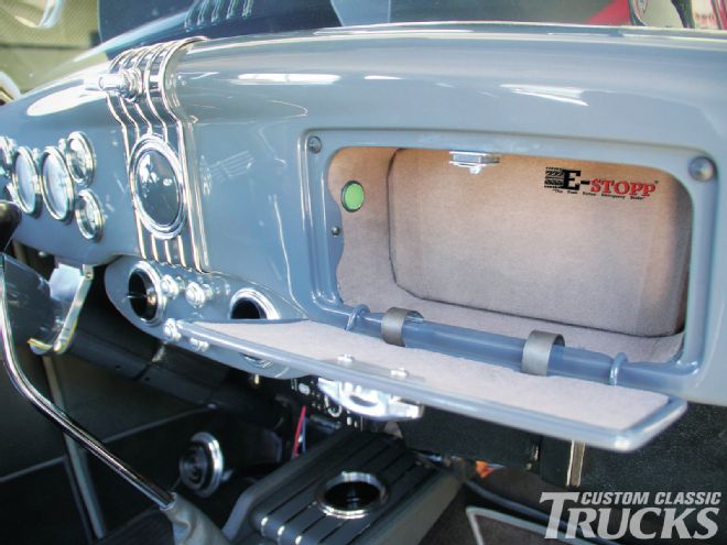
What's cool about the E-Stopp, and what makes it more than just a simple push-button e-brake, is the security aspect of having an electronically actuated parking brake. By hiding the button in an inconspicuous location, such as in a locking glovebox, it becomes nearly impossible to disable the e-brake once set. A would-be thief could get into your truck and fire it up, but he'd have a hard time driving away with a pair of locked-up rear tires. In the case of a failed hydraulic system, it can also be used as an emergency brake by safely engaging the brakes via the mechanical e-brake system. Safety and security built into one system, now that's 21st century technology for ya!
Installing the E-Stopp system is a simple manner of locating the existing e-brake cables and mating them to the actuator, mounting the control box and switch, and wiring the system to a 12-volt source. On most trucks, the install could take anywhere from a few minutes to a few hours, depending on the existing, or lack thereof, e-brake system.
We took an afternoon to install the E-Stopp system, which included running brand-new Lokar emergency brake cables, mounting the actuator, control box and button, and wiring up the system. At the end of the day, we ended up with an e-brake system that not only gave us the safety features we were lacking, but also added a bit of extra security over a standard lever-type system, in about the same time it would have taken to install a traditional e-brake setup.
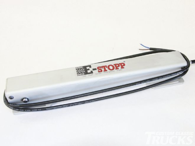
1. Housed in a double-layered, weatherproof aluminum housing, the E-Stopp actuator consists of a worm-drive mechanism capable of pulling a tension up to 600 pounds, wherein it locks upon itself to maintain continuous line pressure.
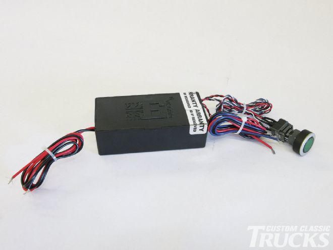
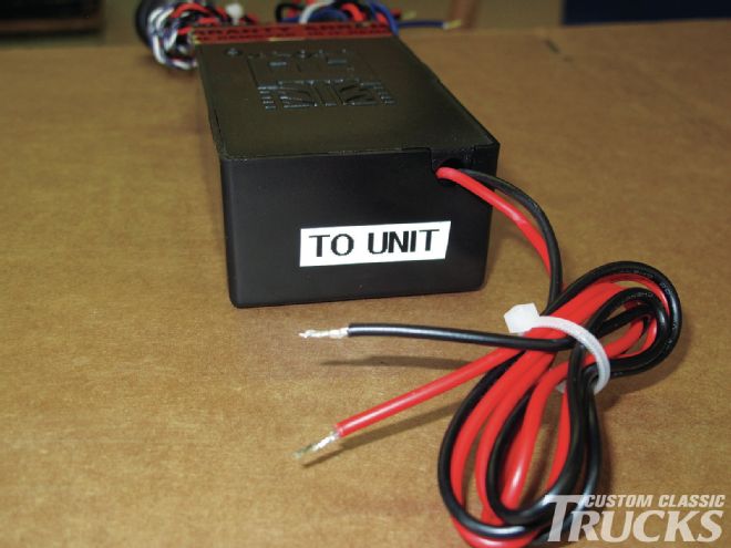
2. The brain of the unit is in the control box, which contains a microcomputer and relays the signal from the LED-equipped pushbutton to the actuator.
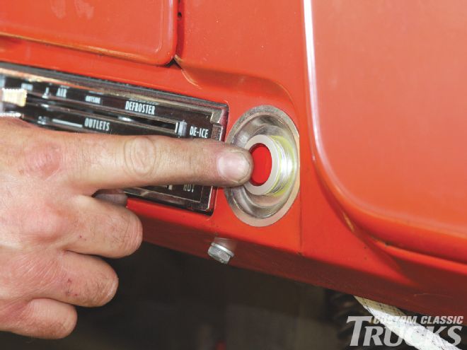
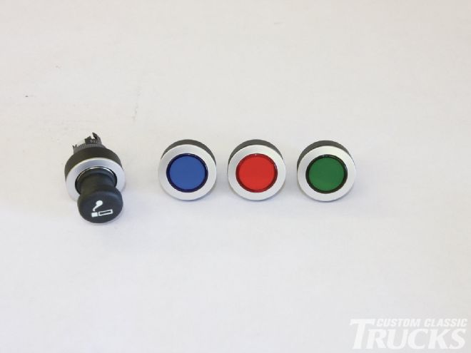
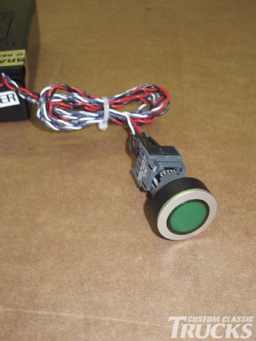
3. The pushbuttons are available in an assortment of LED-lit colors, as well as a faux cigarette lighter that is easily hidden on any dash.
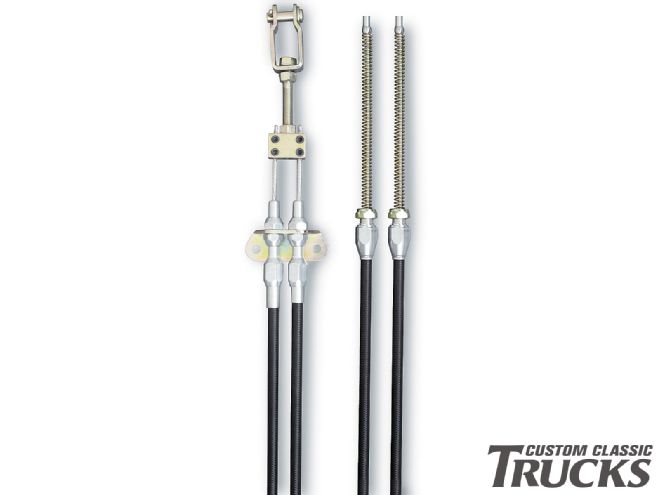
4. For our application, we're using a Lokar universal emergency brake cable kit (EC-80FU) to mate the actuator to the Ford emergency brake mechanisms on the rear disc brakes.
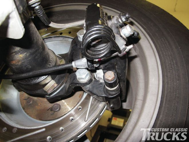
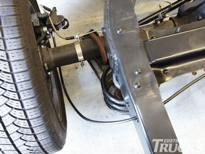
5. It's a simple matter of attaching the housing to the caliper and hooking the cable's clevis in the arm of the e-brake mechanism.
6. Next, it's time to figure out where to mount the actuator. We chose to mount it on the driver-side framerail, where it's well clear of the exhaust and close to the driver side of the dash, making mounting the button on the dash and the control box under the seat a breeze.
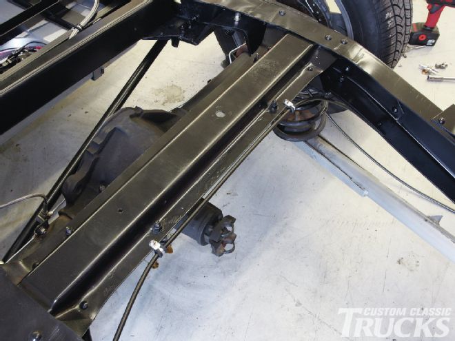
7. Routing the emergency brake lines is pretty straightforward, but slightly different than most stock applications since we're pulling them from one side as opposed to from the center.
8. That requires the passenger side cable to route through the frame and across the rear crossmember.
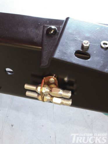
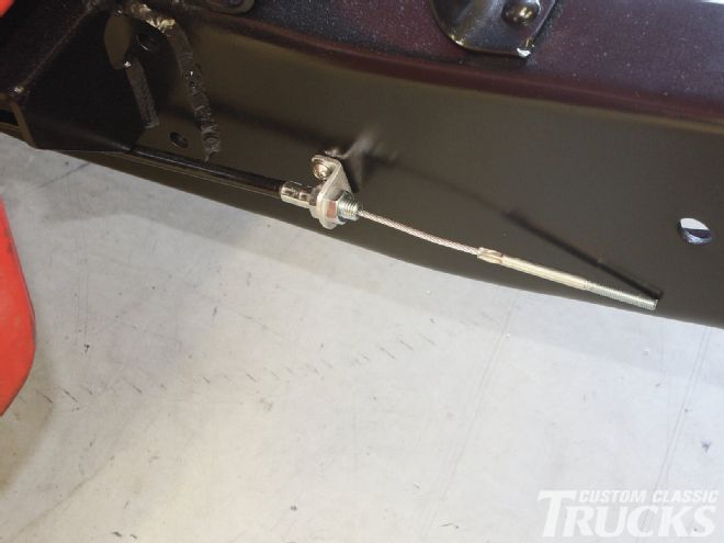
9. With both the cables attached, it's time to locate and mount the cable housing adjustor bracket to the framerail.
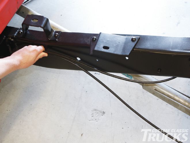
10. This acts as a stop for the front side of the brake cable housings and allows the cable's tension to be adjusted.
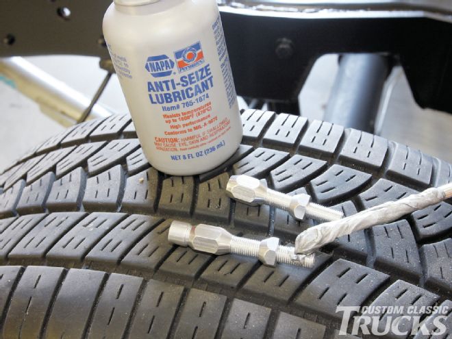
11. To prevent galling of the aluminum threads on the cable adjustors, a dab of anti-seize is a good idea.
12. To support the cable-housing end of the actuator, I fabricated a quick bracket to ensure that the actuator cable lines up properly with the cable housing adjustor and pulls the e-brake cables in a nice, straight line.
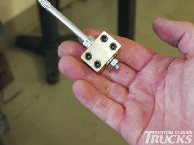
13. Next, I attached the cable block, which is part of the Lokar e-brake cable kit, to the end of the actuator cable using the studded rod and a pair of nuts.
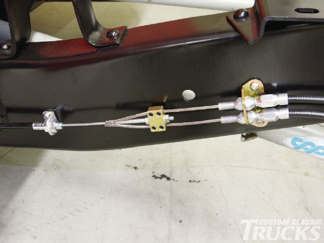
14. Each e-brake cable is then pulled taut through the cable block and fastened in place using the two setscrews.
15 The blue wire coming out of the actuator connects to the black (–) wire coming from the control box, while the brown wire attaches to the red (+) wire.
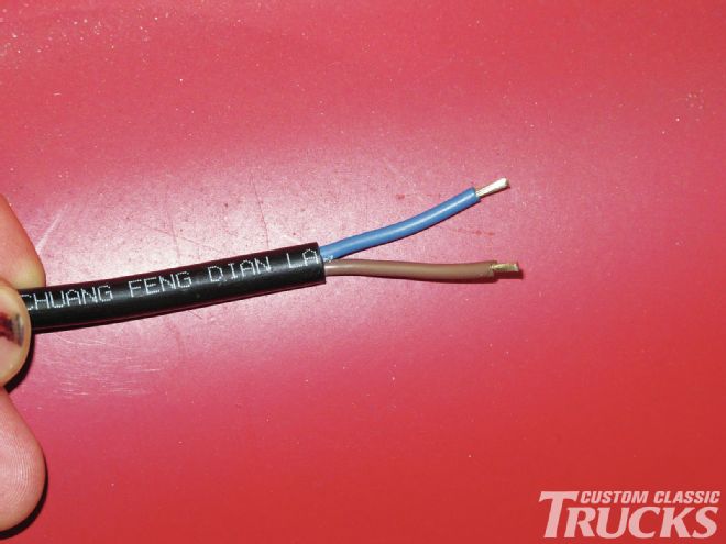
16. When it comes to wiring the unit up, it's pretty simple.
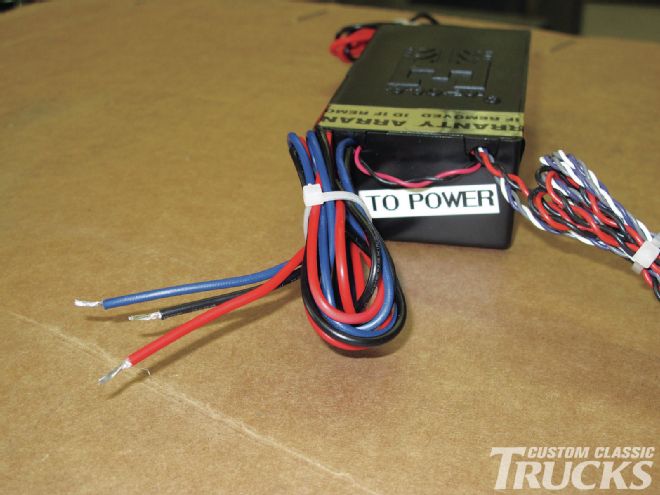
17. On the other end of the control box, the black wire goes to chassis ground, while the red attaches to a 12V+ BAT source. The blue wire is used when the system needs to be disabled during regular use via switched 12V. This is optional and is used to disable the system to prevent any unwanted triggering of the E-Stopp system while the vehicle is in operation, rendering it a parking brake as opposed to a genuine emergency brake.
18. The push-button switch is a simple plug 'n' play design. Simply mount it where desired and plug in the connector.
19. Here's a great example of a custom installation where the owner opted to hide the switch in a lockable glovebox. Simply push the button, lock the glovebox, and leave your car parked with peace of mind that there's one more item of deterrence at work.