
We’re nearing the end of the electrical work on Scarlett, our ’72 coupe project car. After wiring up the fuel injection, replacing the factory harnesses, and converting the headlights to electric rather than vacuum, we have two major areas left to hit: upgrading the lighting and converting the manual crank windows to electric, which we take on this month.
Although we accept certain foibles as part of the experience of owning an older Corvette, the hand crank windows needed to go. Not only is it devilishly hard to reach across the car to lower the passenger-side window; on Scarlett, the driver-side knob always seems to press into the driver’s knee or some other place it ought not. The decisive factor, though, was when the cranks kept either stripping or simply breaking off. At one point we had to jam a long key into the gap of the broken crank to roll the windows down. After we went through three handles in similar fashion, we reached out to Corvette Central for its electric conversion, which contains all the parts required for the conversion, including regulators, motors, switches, and the wiring harness.
While the task may sound daunting, it’s surprisingly simple. The wiring is among the simpler electrical tasks we’ve faced, and since the car was originally equipped to take either manual or electric windows there’s no need to modify anything. The holes are all drilled and the mounting points are already in place.
The most challenging part of the install was figuring out how to take the window assembly apart. Even with the factory assembly and service manuals we resorted to a fair degree of try-and-see to get things loose enough that we could remove the glass from the door and remove the regulator.
For those who aren’t familiar with the intimate workings of window lifts, here’s the short version. The bottom of the window is seated in a track where two arms with rollers connect the track to a cranking mechanism that rolls the window up and down in a pair of vertical channels (one in the front and one in the rear) of the door’s window opening. A removable stop at the top of each channel keeps the window from coming up too far.
In addition to the two fixed vertical channels, there are two horizontal tracks: one mounted along the bottom side of the window and one mounted to the inside of the door. They are connected to each other by the regulator, which is the heart of the window lift system, whether manual or electric. The regulator is an X-shaped piece that pivots in the middle like a pair of scissors. The tops of the two arms of the “X” have rollers that mount in the horizontal track on the bottom of the window, while the rear lower arm of the “X” mounts in the shorter, fixed horizontal track attached to the inside of the door. The forward lower arm is toothed and meshes with the gear mechanism of either the hand crank or the electrical motor. When the lower forward part of the “X” moves up or down, it causes the “X” to either close or spread, making the window move up or down.
To remove it all, we took off the door panel — a fairly simple task — then removed the hand crank mechanism and access panel at the bottom of the door. With that out of the way, we unbolted the two vertical channels and the door-mounted horizontal track, as well as one of the rollers from the window, then removed the glass upwards. Unbolt the regulator, collapse it, and fish it out through the access hole. Reassemble in reverse fashion, and repeat on the other side.
While we’re this deep into it, we’ll clean up the slightly corroded tracks and go ahead and replace the door glass and seals to minimize the risk of leaks. We’ll also insulate the doors, both underneath the door trim panel and inside the door cavity, to reduce sound and heat. We expect plenty of both from the stainless sidepipes sitting right beneath our doors.
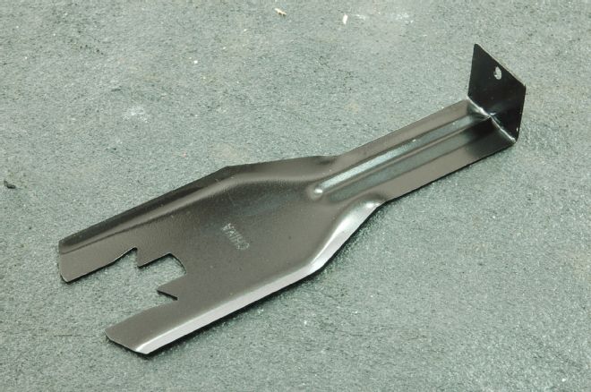
01. We used this tool from Corvette Central to remove the window crank handles. It’s designed to catch the lock ring that holds the handle in place and spread it so the handle can be removed. The door lock knob is held in by a similar arrangement. Both will have to be removed for the door panel to come off.
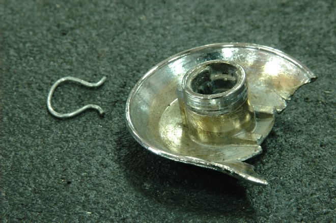
02. The backside of our broken window crank, the latest of three to give it up. The lock ring on the left fits in the slots on the base of the crank handle, and into a matching ring on the toothed stud to which the handle mounts, holding the handle in place.
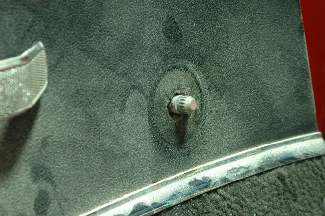
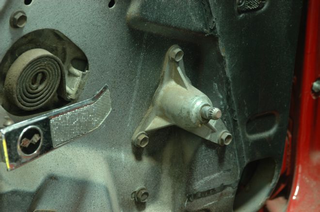
03. The toothed stud to which the window crank handle mounts. While it is possible to just patch the hole left behind when the crank mechanism is removed we’ll be replacing the door panels with new ones when we finish out the rest of the interior.
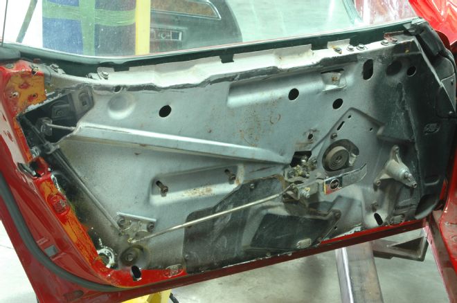
04. To remove the door panel, we removed the screws that hold it in place (including two through the pull handle) and then lifted it upwards and off. It is possible to remove the panel without taking the handle off first, but it’s a lot easier to remove the screw that holds the handle in place then slide it forward off its track. This is what you’ll see once the panel is off.
05. The manual crank mechanism is held in place by three bolts. Remove them and put the whole thing in swap meet pile. The coiled spring visible in the hole to the left is part of the regulator. The new regulator will mount in the same place using different screw holes.
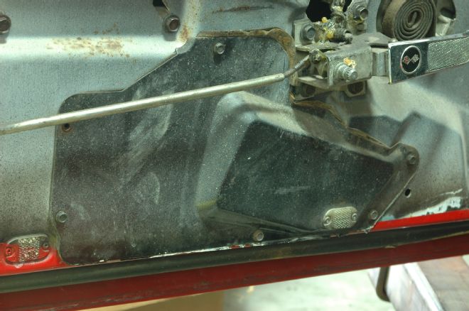
06. This access panel at the bottom of the door has to be removed to get access to the bowels of the window mechanism. It will need to be sealed back to the door when it’s reassembled. Note the axle grease on the door lock mechanism. A previous technician filled the moving parts with grease, making it a slick mess to disassemble.
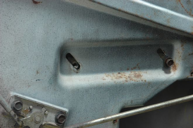
07. The lower horizontal track mounts to the door through these two holes. Note they’re angled slots. This is part of how the window is aligned to make sure it lines up with the window opening in the door.
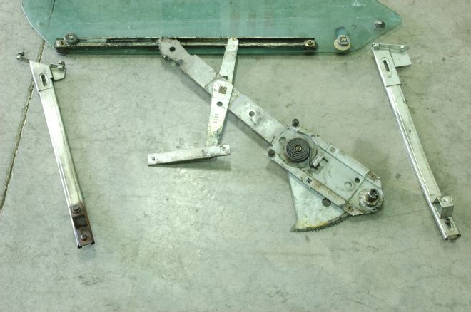
08. The disassembled mechanism of the driver-side door. Note the fore and aft tracks, as well as the long horizontal track mounted to the window and the shorter horizontal track that mounts to the door. The X-shaped part in the middle is the regulator.
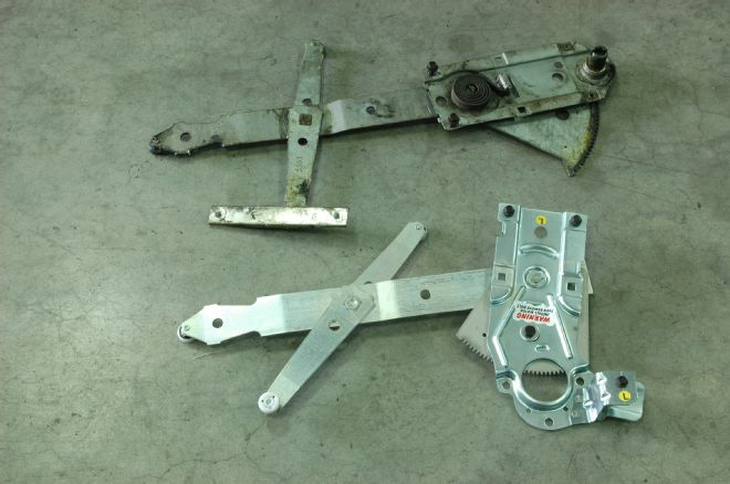
09. The manual regulator (top) and the new electric regulator. Like the manual one, the electric regulator is spring-loaded and comes with a bolt holding the spring in tension for ease of assembly. It’ll need to be removed once the motor is bolted in place.
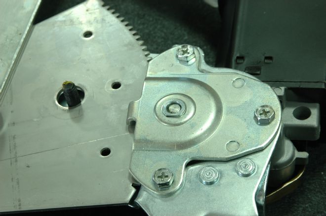
10. The motor mounts to the regulator using this backing plate and bushing, which fits over the end of the motor shaft. The teeth on the shaft will need to be aligned with those on the regulator. We found some fine burrs on the regulator teeth so we hit the teeth on a wire wheel to remove the burrs prior to assembly.
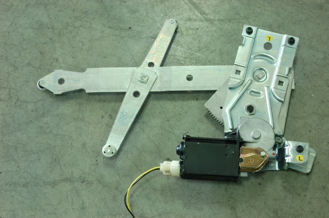
11. The regulator assembly ready for installation in the door. The top two bolts, along with the black bolt on the lower right of the motor bracket, will hold it in place. The fourth black bolt in the middle is the one that will need to be removed prior to final assembly.
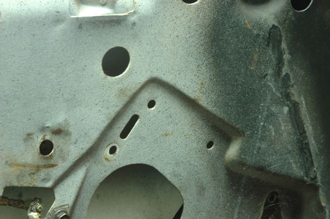
12. The primary mounting points for the new regulator assembly: the two boltholes and the slot (on the left of them) that lines up with a tab on the motor bracket.
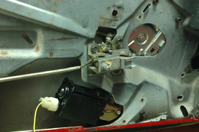
13. The regulator and motor assembly bolted in place in the door. This pretty much wraps up the mechanical part of the work; now it just has to be wired.
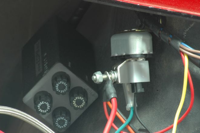
14. factory harness gets power from the horn relay (shown here), which mounts to the rear inner fender on the passenger side of the door. Current goes from here to a circuit breaker and then passes through the firewall into the car.
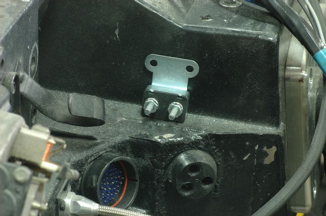
15. Though some of the instructions we saw were in conflict on this point, most suggested the circuit breaker should be mounted on the firewall roughly in this location. One stud receives power from the horn relay while the wire on the other stud passes through the grommet beneath the circuit breaker and into the car, where the harness will also plug into a relay.
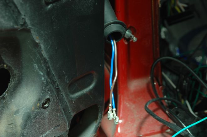
16. Two wires go from the main harness out to each door and pass through a rubber conduit between the jamb and the door. Since the rubber tube is somewhat crimped once it’s in place, we suggest running the wires through it before seating the tube in the door. Since Scarlett originally had manual windows, we first had to push out the plugs the factory used to fill the holes into which the conduit mounts.
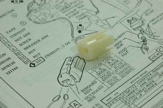
17. The two terminated wires have to be seated into a plastic connector that plugs into the motor. We checked both the instructions that came with the Lectric Limited harness and the factory assembly manual for orientation prior to plugging them in.
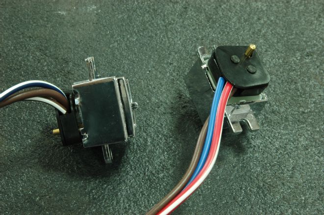
18. The two switches with their respective plugs seated in place. As with all wiring, color is used to indicate which set of wires goes with which window switch.
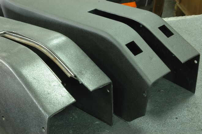
19. Our original parking brake housing (left) shown with the new one provided by Corvette Central. While it’s possible to cut the holes for the electric window switches, our housing was looking a bit shabby so we opted for a new housing with the holes already in place.
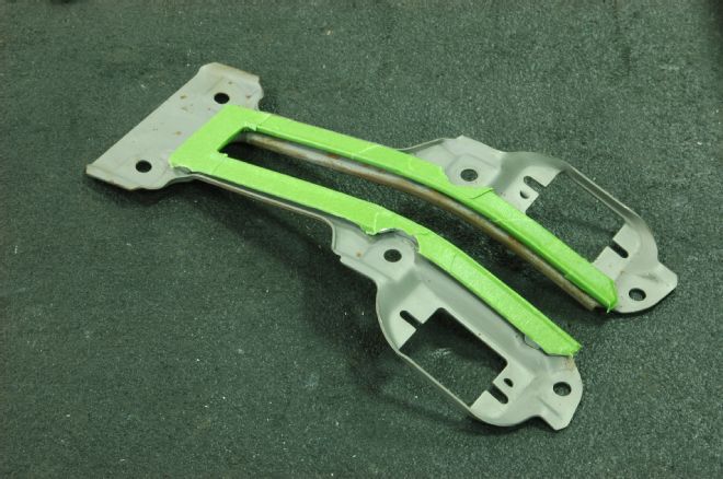
20. Much of the structure of the housing comes from this metal support, which also contains the track in which the dust seal rides. You’ll note there’s a little light corrosion on the bare metal parts. We taped off the bright chrome bits (as shown here) to blast it clean and paint it semi-gloss black.
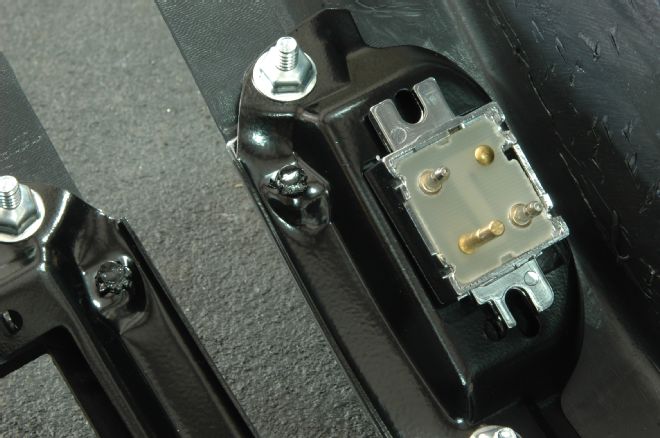
21. The switch, as shown from the rear, in place in the bracket. Both switches are identical. Note that one mounting tab is narrower than the other, which allows the switch to only mount one way in its seat. Also note the speed nuts that hold the bracket in place on the studs are molded into the parking brake housing.
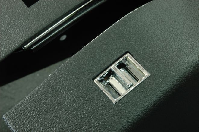
22. The switch mounted in place on the parking brake housing.