You probably never give a second thought to the driveshaft under your car-that is until you have to. And although we know a few people who make their own, when it comes time to connect the transmission to the rearend, most of us will either drop the car off at a driveshaft shop or provide them with a few measurements, collect the finished piece, and bolt it in place.
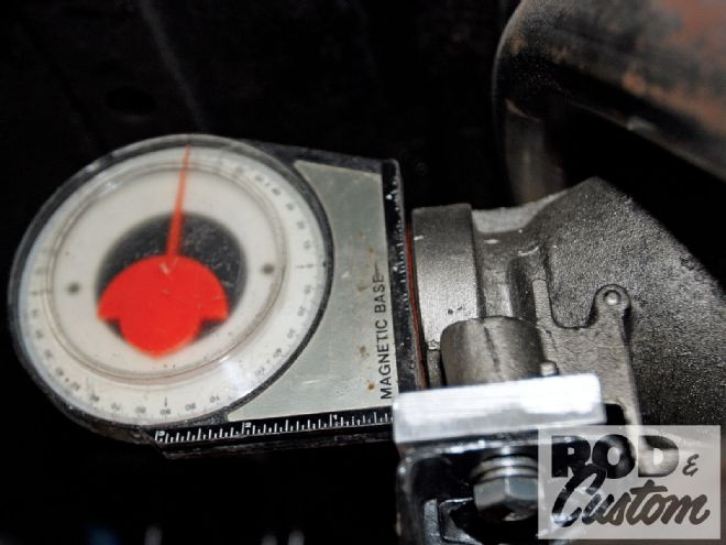 Using a magnetic protractor against the rear face of the transmission tailhousing, I set the output 'shaft angle at 4 degrees. Note the aluminum spacer between the mount and the casing to raise the rear.
There are many times when the driveshaft vibration can be felt in a freshly finished project, sometimes throughout the rpm range, and sometimes at specific speeds. There are numerous reasons and causes, all of which could have been avoided if the drivetrain, and its associated angles, had been planned properly from the outset. A basic rule of thumb when installing an engine is to have the base of the carburetor, or the carburetor mounting surface on the intake manifold, level, which equates to the motor and trans being mounted at an approximate 3-degree downward angle toward the rear of the car. All well and good so far, but how many mount the rearend at a similar angle, this time upward toward the front of the car? This is known as pinion angle, and is extremely important if powertrain vibrations are to be avoided.
With the above angles identical, the centerlines of the rearend pinion 'shaft and the transmission will be parallel, though not in a straight line from the pinion to the transmission output 'shaft. An imaginary extension of the trans centerline will pass under the pinion, while the same for the pinion will pass over the top of the trans tailshaft. This is fine, so long as the angle through the U-joints is 3 degrees or less. You can go as much as 5 degrees, or even as low as 0, but according to Greg Frick at Inland Empire Driveline, something between 0 and 3 degrees seems to run smoothest.
So you can see that mounting the transmission and rearend correctly is important at an early stage of any project, and once finished, the pinion angle should be rechecked and adjusted if necessary. The type of suspension used will offer varying degrees of difficulty when it comes to adjustability. Leaf-sprung cars can have angled shims added between the spring and axle; four-link cars can have the upper and lower links lengthened or shortened. But a ladder bar-equipped car will mean the axle brackets or ladder bar front mounts will need relocating. You may be able to fit a shim between the trans and its mount to lessen the trans angle instead, but it can't be increased!
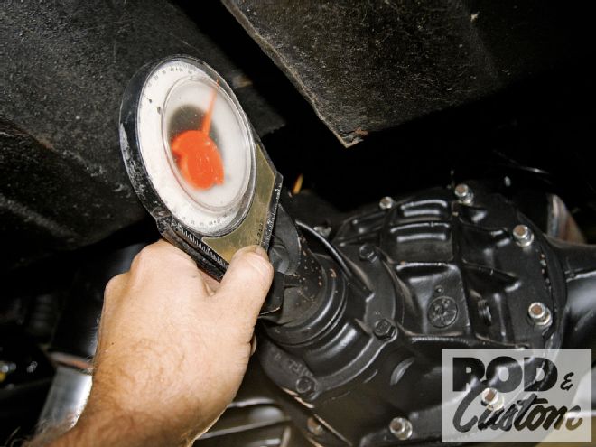 Though obviously shown once everything was fabricated, I used the same protractor to set the pinion angle on the Currie 8-inch before the axle saddles were welded to the casing.
When I installed the motor and trans on our project '49 Chevy I used the engine mounts that came on the Chassis Engineering crossmember, and a Walton Fabrications trans crossmember. The latter is designed to be used with the same company's engine mounts, and the Chassis Engineering motor mounts are higher, so I added a shim under the trans mount to get the trans angle below 5 degrees, settling at 4 degrees. A similar angle was built into the rearend saddles when they were welded to the axle casing.
With the drivetrain angles correct, a further problem arose with the RideTech suspension on "full drop", in that the pinion yoke slightly contacted the rear end of the trans tunnel. I elected to wait until the driveshaft was fitted to see just how much of the tunnel would need replacing, despite it having been raised once, several years ago. The point here is to install your driveshaft as early in a build as possible, so as to avoid having to move chassis components or bodywork for clearance.
I went to Inland Empire Driveline for my driveshaft, having been impressed with its easy-to-understand literature, and very concise form explaining how to measure for a driveshaft, which can be filled in and sent to the company, who in turn can fabricate a 'shaft to your precise dimensions. Inland Empire can supply 'shafts in steel, aluminum, or carbon fiber, as well as associated components such as yokes, U-joints, U-bolts, and center bearing supports for two-piece driveshafts. It seems at just over 57 inches my driveshaft is a little on the long side, but not so long that a two-piece 'shaft was advised. Also, thanks to my Classic Performance Products trailing arms, and their pivot points a long way from the rearend, the difference in length from the pinion to the trans tailshaft at the upper and lower limits of suspension travel differed by a mere 5/16 inch, though Inland Empire Driveline offers 'shafts with sliding joints, common among the lowrider fraternity with long travel hydraulic setups and short control arms. For more information on when a two-piece 'shaft is required, check out the tech section on our website (search for Two Piece Driveshaft Technology at www.rodandcustommagazine.com), but long spans, limited space (two-piece 'shafts are generally smaller diameter than one-piece), and smoother running all play their part.
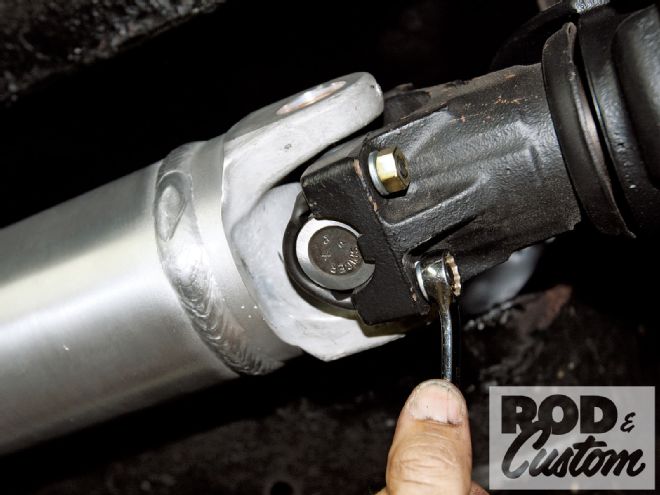
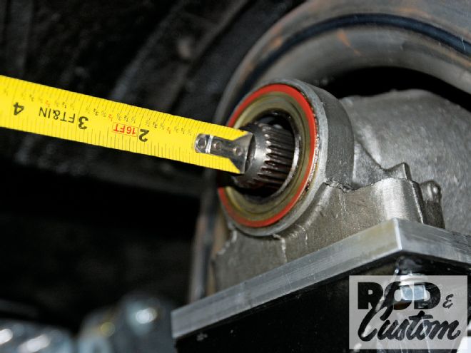 Following Inland Empire Driveline's instruction booklet, I measured from the end of the output 'shaft to the flat surface on the pinion yoke where the U-bolts pass through. This measured 57 5/16 inches. I also measured how far (5/8 inch) the output 'shaft extended from the end of the casing.